参数资料
| 型号: | XIO2200AGGW |
| 厂商: | Texas Instruments |
| 文件页数: | 105/202页 |
| 文件大小: | 0K |
| 描述: | IC PCI-EXPRESS/BUS BRIDGE 176BGA |
| 产品培训模块: | PCI Express Basics |
| 标准包装: | 126 |
| 应用: | PCI Express 至 PCI 转换桥 |
| 接口: | PCI |
| 电源电压: | 1.35 V ~ 1.65 V,3 V ~ 3.6 V |
| 封装/外壳: | 176-LFBGA |
| 供应商设备封装: | 176-BGA MICROSTAR(15x15) |
| 包装: | 托盘 |
| 安装类型: | 表面贴装 |
| 产品目录页面: | 882 (CN2011-ZH PDF) |
| 配用: | XIO2200AEVM-ND - XIO2200AEVM |
| 其它名称: | 296-19617 |
第1页第2页第3页第4页第5页第6页第7页第8页第9页第10页第11页第12页第13页第14页第15页第16页第17页第18页第19页第20页第21页第22页第23页第24页第25页第26页第27页第28页第29页第30页第31页第32页第33页第34页第35页第36页第37页第38页第39页第40页第41页第42页第43页第44页第45页第46页第47页第48页第49页第50页第51页第52页第53页第54页第55页第56页第57页第58页第59页第60页第61页第62页第63页第64页第65页第66页第67页第68页第69页第70页第71页第72页第73页第74页第75页第76页第77页第78页第79页第80页第81页第82页第83页第84页第85页第86页第87页第88页第89页第90页第91页第92页第93页第94页第95页第96页第97页第98页第99页第100页第101页第102页第103页第104页当前第105页第106页第107页第108页第109页第110页第111页第112页第113页第114页第115页第116页第117页第118页第119页第120页第121页第122页第123页第124页第125页第126页第127页第128页第129页第130页第131页第132页第133页第134页第135页第136页第137页第138页第139页第140页第141页第142页第143页第144页第145页第146页第147页第148页第149页第150页第151页第152页第153页第154页第155页第156页第157页第158页第159页第160页第161页第162页第163页第164页第165页第166页第167页第168页第169页第170页第171页第172页第173页第174页第175页第176页第177页第178页第179页第180页第181页第182页第183页第184页第185页第186页第187页第188页第189页第190页第191页第192页第193页第194页第195页第196页第197页第198页第199页第200页第201页第202页
Electrical Characteristics
180
March 5 2007 June 2011
SCPS154C
11. A TRX-EYE = 0.40 UI provides for a total sum of 0.60 UI deterministic and random jitter budget for the transmitter and interconnect
collected any 250 consecutive UIs. The TRX-EYE-MEDIAN-to-MAX-JITTER specification ensures a jitter distribution in which the median
and the maximum deviation from the median is less than half of the total UI jitter budget collected over any 250 consecutive TX UIs.
It must be noted that the median is not the same as the mean. The jitter median describes the point in time where the number of
jitter points on either side is approximately equal as opposed to the averaged time value. If the clocks to the RX and TX are not derived
from the same reference clock, then the TX UI recovered from 3500 consecutive UIs must be used as the reference for the eye
diagram.
12. The receiver input impedance results in a differential return loss greater than or equal to 15 dB with the P line biased to 300 mV and
the N line biased to 300 mV and a common mode return loss greater than or equal to 6 dB (no bias required) over a frequency range
of 50 MHz to 1.25 GHz. This input impedance requirement applies to all valid input levels. The reference impedance for return loss
measurements for is 50 Ω to ground for both the P and N line (i.e., as measured by a Vector Network Analyzer with 50-Ω probes).
The series capacitors CTX is optional for the return loss measurement.
13. Impedance during all link training status state machine (LTSSM) states. When transitioning from a PCI Express reset to the detect
state (the initial state of the LTSSM) there is a 5-ms transition time before receiver termination values must be met on the
unconfigured lane of a port.
14. The RX dc common mode impedance that exists when no power is present or PCI Express reset is asserted. This helps ensure that
the receiver detect circuit does not falsely assume a receiver is powered on when it is not. This term must be measured at 300 mV
above the RX ground.
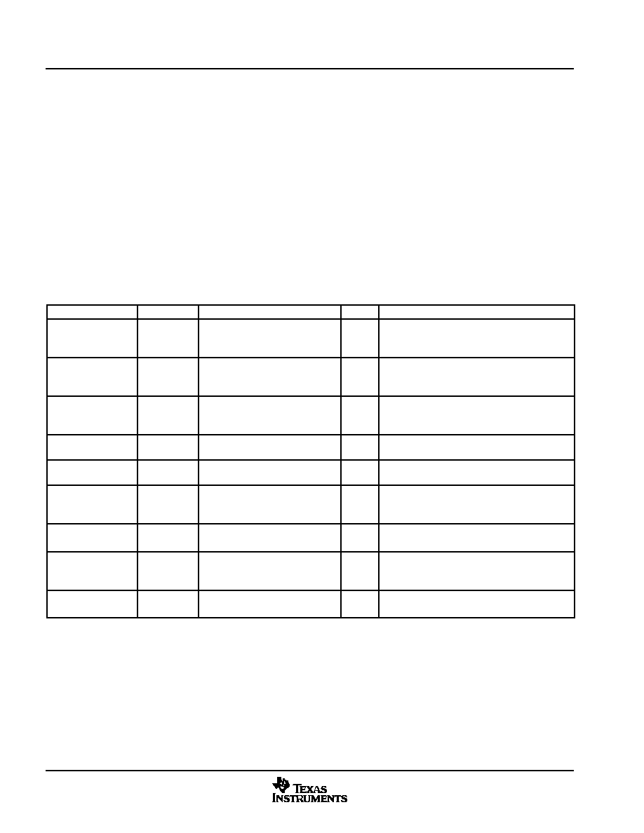
11.5 PCI Express Differential Reference Clock Input Ranges
PARAMETER
TERMINALS
MIN
NOM
MAX
UNITS
COMMENTS
fIN-DIFF
Differential input
frequency
REFCLK+
REFCLK
100
MHz
The input frequency is 100 MHz + 300 ppm and
2800 ppm including SSC-dictated variations.
fIN-SE
Single-ended input
frequency
REFCLK+
125
MHz
The input frequency is 125 MHz + 300 ppm and
300 ppm.
VRX-DIFFp-p
Differential input
peak-to-peak voltage
REFCLK+
REFCLK
0.175
1.200
V
VRX-DIFFp-p = 2*|VREFCLK+ VREFCLK|
VIH-SE
REFCLK+
0.7 VDD_33
VDD_33
V
Single-ended, reference clock mode high-level
input voltage
VIL-SE
REFCLK+
0
0.3 VDD_33
V
Single-ended, reference clock mode low-level
input voltage
VRX-CM-ACp
AC peak common
mode input voltage
REFCLK+
REFCLK
140
mV
VRX-CM-ACp = RMS(|VREFCLK+ + VREFCLK|/2 –
VRX-CM-DC)
VRX-CM-DC = DC(avg) of |VREFCLK+ + VREFCLK|/2
Duty cycle
REFCLK+
REFCLK
40%
60%
Differential and single-ended waveform input duty
cycle
ZRX-DIFF-DC
DC differential input
impedance
REFCLK+
REFCLK
20
kΩ
REFCLK+/ dc differential mode impedance
ZRX-DC
DC input impedance
REFCLK+
REFCLK
20
kΩ
REFCLK+ dc single-ended mode impedance
NOTE 15: The XIO2200A is compliant with the defined system jitter models for a PCI-Express reference clock and associated TX/RX link. These
system jitter models are described in the PCI-Express Jitter Modeling, Revision 1.0RD document. Any usage of the XIO2200A in a
system configuration that does not conform to the defined system jitter models requires the system designer to validate the system jitter
budgets.
Not Recommended for New Designs
相关PDF资料 |
PDF描述 |
|---|---|
| XIO2200AZGW | IC PCI-EXPRESS/BUS BRIDGE 176BGA |
| XPC823ZT81B2T | IC MPU POWERQUICC 81MHZ 256-PBGA |
| XPC8240RZU250E | MCU HOST PROCESSOR 352-TBGA |
| XQ6SLX150T-3CSG484I | IC FPGA SPARTAN-6Q 484-CSBGA |
| XR16C2550IJ-F | IC UART FIFO 16B DUAL 44PLCC |
相关代理商/技术参数 |
参数描述 |
|---|---|
| XIO2200AZGW | 功能描述:外围驱动器与原件 - PCI PCI Exp-PCI Bus Trans Bridge RoHS:否 制造商:PLX Technology 工作电源电压: 最大工作温度: 安装风格:SMD/SMT 封装 / 箱体:FCBGA-1156 封装:Tray |
| XIO2200AZGW | 制造商:Texas Instruments 功能描述:PCI Express to PCI Bus Converter IC |
| XIO2200AZHH | 功能描述:外围驱动器与原件 - PCI PCI Exp-PCI Bus Trans Bridge RoHS:否 制造商:PLX Technology 工作电源电压: 最大工作温度: 安装风格:SMD/SMT 封装 / 箱体:FCBGA-1156 封装:Tray |
| XIO2200GGW | 功能描述:IC PCI-EXPRESS/BUS BRIDGE 176BGA RoHS:是 类别:集成电路 (IC) >> 接口 - 专用 系列:- 标准包装:3,000 系列:- 应用:PDA,便携式音频/视频,智能电话 接口:I²C,2 线串口 电源电压:1.65 V ~ 3.6 V 封装/外壳:24-WQFN 裸露焊盘 供应商设备封装:24-QFN 裸露焊盘(4x4) 包装:带卷 (TR) 安装类型:表面贴装 产品目录页面:1015 (CN2011-ZH PDF) 其它名称:296-25223-2 |
| XIO2200ZGW | 功能描述:IC PCI-EXPRESS/BUS BRIDGE 176BGA RoHS:是 类别:集成电路 (IC) >> 接口 - 专用 系列:- 标准包装:3,000 系列:- 应用:PDA,便携式音频/视频,智能电话 接口:I²C,2 线串口 电源电压:1.65 V ~ 3.6 V 封装/外壳:24-WQFN 裸露焊盘 供应商设备封装:24-QFN 裸露焊盘(4x4) 包装:带卷 (TR) 安装类型:表面贴装 产品目录页面:1015 (CN2011-ZH PDF) 其它名称:296-25223-2 |
发布紧急采购,3分钟左右您将得到回复。