- 您现在的位置:买卖IC网 > PDF目录16527 > XR20V2172L64-0B-EB (Exar Corporation)EVAL BOARD FOR XR20V2170 64QFN PDF资料下载
参数资料
| 型号: | XR20V2172L64-0B-EB |
| 厂商: | Exar Corporation |
| 文件页数: | 24/51页 |
| 文件大小: | 0K |
| 描述: | EVAL BOARD FOR XR20V2170 64QFN |
| 标准包装: | 1 |
| 系列: | * |
第1页第2页第3页第4页第5页第6页第7页第8页第9页第10页第11页第12页第13页第14页第15页第16页第17页第18页第19页第20页第21页第22页第23页当前第24页第25页第26页第27页第28页第29页第30页第31页第32页第33页第34页第35页第36页第37页第38页第39页第40页第41页第42页第43页第44页第45页第46页第47页第48页第49页第50页第51页
XR20V2172
30
TWO CHANNEL I2C/SPI UART WITH 64-BYTE FIFO AND RS232 TRANSCEIVER
REV. 1.0.2
MCR[2]: OP1# / TCR and TLR Enable
OP1# is not available as an output pin on the V2172. But it is available for use during Internal Loopback Mode
(MCR[4] = 1). In the Internal Loopback Mode, this bit is used to write the state of the modem RI# interface
signal.
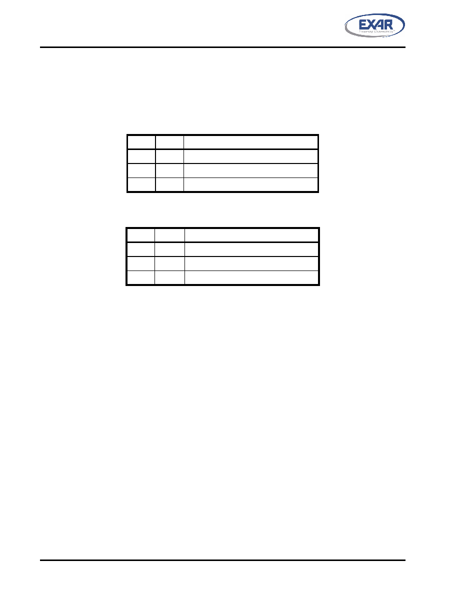
This bit is also used to select between the MSR and TCR registers at address offset 0x6 and the SPR and TLR
registers at address offset 0x7. Table 12 and Table 13 below shows how these registers are accessed.
TABLE 12: REGISTER AT ADDRESS OFFSET 0X6
EFR[4] MCR[2] Register at Address Offset 0x6
0
X
Modem Status Register (MSR)
1
0
Modem Status Register (MSR)
1
Trigger Control Register (TCR)
TABLE 13: REGISTER AT ADDRESS OFFSET 0X7
EFR[4] MCR[2] Register at Address Offset 0x7
0
X
Scratchpad Register (SPR)
1
0
Scratchpad Register (SPR)
1
Trigger Level Register (TLR)
MCR[3]: OP2# Output
OP2# is not available as an output on the V2172 but can be controlled in internal loopback mode.
Logic 0 = OP2# output set HIGH(default).
Logic 1 = OP2# output set LOW.
MCR[4]: Internal Loopback Enable
Logic 0 = Disable loopback mode (default).
Logic 1 = Enable local loopback mode, see loopback section and Figure 14.
MCR[5]: Xon-Any Enable (requires EFR bit-4=1 to write to this bit)
Logic 0 = Disable Xon-Any function (default).
Logic 1 = Enable Xon-Any function. In this mode, any RX character received will resume transmit operation.
The RX character will be loaded into the RX FIFO, unless the RX character is an Xon or Xoff character and
the V2172 is programmed to use the Xon/Xoff flow control.
MCR[6]: Infrared Encoder/Decoder Enable
Logic 0 = Enable the standard modem receive and transmit input/output interface (default).
Logic 1 = Enable infrared IrDA receive and transmit inputs/outputs. The TX/RX output/input are routed to the
infrared encoder/decoder. The data input and output levels conform to the IrDA infrared interface requirement.
While in this mode, the infrared TX output will be idling LOW. SEE”INFRARED MODE (UART CHANNEL B
相关PDF资料 |
PDF描述 |
|---|---|
| UPM1E181MPD6TD | CAP ALUM 180UF 25V 20% RADIAL |
| AQ1051N8S-T | INDUCTOR 1.8NH 760MA 0402 SMD |
| UPS2G3R3MPD1TD | CAP ALUM 3.3UF 400V 20% RADIAL |
| XR20V2172L64-0A-EB | EVAL BOARD FOR XR20V2170 64QFN |
| UPJ1C331MPD6TD | CAP ALUM 330UF 16V 20% RADIAL |
相关代理商/技术参数 |
参数描述 |
|---|---|
| XR-210 | 制造商:EXAR 制造商全称:EXAR 功能描述:FSK MODULATOR / DEMODULATOR |
| XR-2100CJ | 制造商:未知厂家 制造商全称:未知厂家 功能描述:MODEM |
| XR-2100CP | 制造商:未知厂家 制造商全称:未知厂家 功能描述:MODEM |
| XR-2103 | 制造商:EXAR 制造商全称:EXAR 功能描述:FSK Modem Filter |
| XR-2103A | 制造商:EXAR 制造商全称:EXAR 功能描述:FSK Modem Filter |
发布紧急采购,3分钟左右您将得到回复。