- 您现在的位置:买卖IC网 > PDF目录16527 > XR20V2172L64-0B-EB (Exar Corporation)EVAL BOARD FOR XR20V2170 64QFN PDF资料下载
参数资料
| 型号: | XR20V2172L64-0B-EB |
| 厂商: | Exar Corporation |
| 文件页数: | 30/51页 |
| 文件大小: | 0K |
| 描述: | EVAL BOARD FOR XR20V2170 64QFN |
| 标准包装: | 1 |
| 系列: | * |
第1页第2页第3页第4页第5页第6页第7页第8页第9页第10页第11页第12页第13页第14页第15页第16页第17页第18页第19页第20页第21页第22页第23页第24页第25页第26页第27页第28页第29页当前第30页第31页第32页第33页第34页第35页第36页第37页第38页第39页第40页第41页第42页第43页第44页第45页第46页第47页第48页第49页第50页第51页
XR20V2172
36
TWO CHANNEL I2C/SPI UART WITH 64-BYTE FIFO AND RS232 TRANSCEIVER
REV. 1.0.2
4.21
Enhanced Feature Register (EFR)
Enhanced features are enabled or disabled using this register. Bit 0-3 provide single or dual consecutive
character software flow control selection (see Table 15). When the Xon1 and Xon2 and Xoff1 and Xoff2 modes
are selected, the double 8-bit words are concatenated into two sequential characters. Caution: note that
whenever changing the TX or RX flow control bits, always reset all bits back to logic 0 (disable) before
programming a new setting.
EFR[3:0]: Software Flow Control Select
Single character and dual sequential characters software flow control is supported. Combinations of software
flow control can be selected by programming these bits.
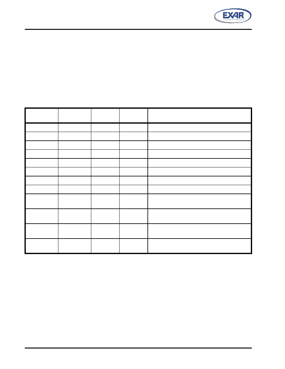
TABLE 15: SOFTWARE FLOW CONTROL FUNCTIONS
EFR BIT-3
CONT-3
EFR BIT-2
CONT-2
EFR BIT-1
CONT-1
EFR BIT-0
CONT-0
TRANSMIT AND RECEIVE SOFTWARE FLOW CONTROL
0
No TX and RX flow control (default and reset)
0
X
No transmit flow control
1
0
X
Transmit Xon1, Xoff1
0
1
X
Transmit Xon2, Xoff2
1
X
Transmit Xon1 and Xon2, Xoff1 and Xoff2
X
0
No receive flow control
X
1
0
Receiver compares Xon1, Xoff1
X
0
1
Receiver compares Xon2, Xoff2
1
0
1
Transmit Xon1, Xoff1
Receiver compares Xon1 or Xon2, Xoff1 or Xoff2
0
1
Transmit Xon2, Xoff2
Receiver compares Xon1 or Xon2, Xoff1 or Xoff2
1
Transmit Xon1 and Xon2, Xoff1 and Xoff2,
Receiver compares Xon1 and Xon2, Xoff1 and Xoff2
0
1
No transmit flow control,
Receiver compares Xon1 and Xon2, Xoff1 and Xoff2
EFR[4]: Enhanced Function Bits Enable
Enhanced function control bit. This bit enables IER bits 4-7, ISR bits 4-5, FCR bits 4-5, MCR bits 2 and 5-7,
TCR, TLR and DLD to be modified. After modifying any enhanced bits, EFR bit-4 can be set to a logic 0 to latch
the new values. This feature prevents legacy software from altering or overwriting the enhanced functions once
set. Normally, it is recommended to leave it enabled, logic 1.
Logic 0 = modification disable/latch enhanced features. IER bits 4-7, ISR bits 4-5, FCR bits 4-5, MCR bits 2
and 5-7, and DLD are saved to retain the user settings. After a reset, the IER bits 4-7, ISR bits 4-5, FCR bits
4-5, MCR bits 5-7, and DLD are set to a logic 0 to be compatible with ST16C550 mode (default).
Logic 1 = Enables the above-mentioned register bits to be modified by the user.
EFR[5]: Special Character Detect Enable
Logic 0 = Special Character Detect Disabled (default).
相关PDF资料 |
PDF描述 |
|---|---|
| UPM1E181MPD6TD | CAP ALUM 180UF 25V 20% RADIAL |
| AQ1051N8S-T | INDUCTOR 1.8NH 760MA 0402 SMD |
| UPS2G3R3MPD1TD | CAP ALUM 3.3UF 400V 20% RADIAL |
| XR20V2172L64-0A-EB | EVAL BOARD FOR XR20V2170 64QFN |
| UPJ1C331MPD6TD | CAP ALUM 330UF 16V 20% RADIAL |
相关代理商/技术参数 |
参数描述 |
|---|---|
| XR-210 | 制造商:EXAR 制造商全称:EXAR 功能描述:FSK MODULATOR / DEMODULATOR |
| XR-2100CJ | 制造商:未知厂家 制造商全称:未知厂家 功能描述:MODEM |
| XR-2100CP | 制造商:未知厂家 制造商全称:未知厂家 功能描述:MODEM |
| XR-2103 | 制造商:EXAR 制造商全称:EXAR 功能描述:FSK Modem Filter |
| XR-2103A | 制造商:EXAR 制造商全称:EXAR 功能描述:FSK Modem Filter |
发布紧急采购,3分钟左右您将得到回复。