- 您现在的位置:买卖IC网 > PDF目录16527 > XR20V2172L64-0B-EB (Exar Corporation)EVAL BOARD FOR XR20V2170 64QFN PDF资料下载
参数资料
| 型号: | XR20V2172L64-0B-EB |
| 厂商: | Exar Corporation |
| 文件页数: | 6/51页 |
| 文件大小: | 0K |
| 描述: | EVAL BOARD FOR XR20V2170 64QFN |
| 标准包装: | 1 |
| 系列: | * |
第1页第2页第3页第4页第5页当前第6页第7页第8页第9页第10页第11页第12页第13页第14页第15页第16页第17页第18页第19页第20页第21页第22页第23页第24页第25页第26页第27页第28页第29页第30页第31页第32页第33页第34页第35页第36页第37页第38页第39页第40页第41页第42页第43页第44页第45页第46页第47页第48页第49页第50页第51页
XR20V2172
14
TWO CHANNEL I2C/SPI UART WITH 64-BYTE FIFO AND RS232 TRANSCEIVER
REV. 1.0.2
2.9
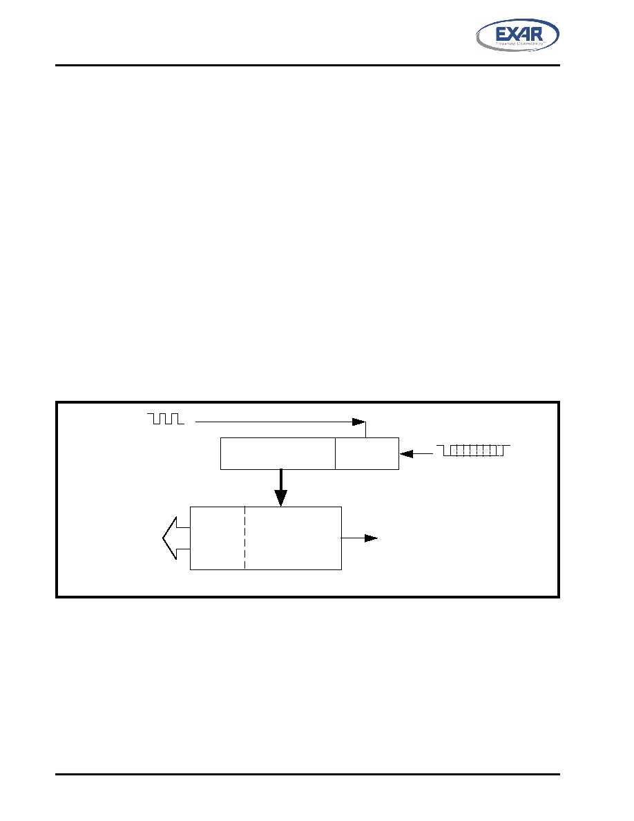
Receiver
The receiver section contains an 8-bit Receive Shift Register (RSR) and 64 bytes of FIFO which includes a
byte-wide Receive Holding Register (RHR). The RSR uses the 16X/8X/4X clock (DLD [5:4]) for timing. It
verifies and validates every bit on the incoming character in the middle of each data bit. On the falling edge of
a start or false start bit, an internal receiver counter starts counting at the 16X/8X/4X clock rate. After 8 clocks
(or 4 if 8X or 2 if 4X) the start bit period should be at the center of the start bit. At this time the start bit is
sampled and if it is still a logic 0 it is validated. Evaluating the start bit in this manner prevents the receiver from
assembling a false character. The rest of the data bits and stop bits are sampled and validated in this same
manner to prevent false framing. If there were any error(s), they are reported in the LSR register bits 2-4. Upon
unloading the receive data byte from RHR, the receive FIFO pointer is bumped and the error tags are
immediately updated to reflect the status of the data byte in RHR register. RHR can generate a receive data
ready interrupt upon receiving a character or delay until it reaches the FIFO trigger level. Furthermore, data
delivery to the host is guaranteed by a receive data ready time-out interrupt when data is not received for 4
word lengths as defined by LCR[1:0] plus 12 bits time. This is equivalent to 3.7-4.6 character times. The RHR
interrupt is enabled by IER bit-0.
2.9.1
Receive Holding Register (RHR) - Read-Only
The Receive Holding Register is an 8-bit register that holds a receive data byte from the Receive Shift
Register. It provides the receive data interface to the host processor. The RHR register is part of the receive
FIFO of 64 bytes by 11-bits wide, the 3 extra bits are for the 3 error tags to be reported in LSR register. When
the FIFO is enabled by FCR bit-0, the RHR contains the first data character received by the FIFO. After the
RHR is read, the next character byte is loaded into the RHR and the errors associated with the current data
byte are immediately updated in the LSR bits 2-4.
FIGURE 10. RECEIVER OPERATION IN NON-FIFO MODE
R eceive D ata Shift
R egister (R SR)
Receive
D ata Byte
and Errors
R H R Interrupt (ISR bit-2)
Receive Data
H olding R egister
(R H R)
R XFIFO 1
16X or 8X or 4X C lock
( D LD[5:4] )
R eceive Data Characters
D ata Bit
Validation
Error
Tags in
LSR bits
4:2
相关PDF资料 |
PDF描述 |
|---|---|
| UPM1E181MPD6TD | CAP ALUM 180UF 25V 20% RADIAL |
| AQ1051N8S-T | INDUCTOR 1.8NH 760MA 0402 SMD |
| UPS2G3R3MPD1TD | CAP ALUM 3.3UF 400V 20% RADIAL |
| XR20V2172L64-0A-EB | EVAL BOARD FOR XR20V2170 64QFN |
| UPJ1C331MPD6TD | CAP ALUM 330UF 16V 20% RADIAL |
相关代理商/技术参数 |
参数描述 |
|---|---|
| XR-210 | 制造商:EXAR 制造商全称:EXAR 功能描述:FSK MODULATOR / DEMODULATOR |
| XR-2100CJ | 制造商:未知厂家 制造商全称:未知厂家 功能描述:MODEM |
| XR-2100CP | 制造商:未知厂家 制造商全称:未知厂家 功能描述:MODEM |
| XR-2103 | 制造商:EXAR 制造商全称:EXAR 功能描述:FSK Modem Filter |
| XR-2103A | 制造商:EXAR 制造商全称:EXAR 功能描述:FSK Modem Filter |
发布紧急采购,3分钟左右您将得到回复。