- 您现在的位置:买卖IC网 > PDF目录16527 > XR20V2172L64-0B-EB (Exar Corporation)EVAL BOARD FOR XR20V2170 64QFN PDF资料下载
参数资料
| 型号: | XR20V2172L64-0B-EB |
| 厂商: | Exar Corporation |
| 文件页数: | 3/51页 |
| 文件大小: | 0K |
| 描述: | EVAL BOARD FOR XR20V2170 64QFN |
| 标准包装: | 1 |
| 系列: | * |
第1页第2页当前第3页第4页第5页第6页第7页第8页第9页第10页第11页第12页第13页第14页第15页第16页第17页第18页第19页第20页第21页第22页第23页第24页第25页第26页第27页第28页第29页第30页第31页第32页第33页第34页第35页第36页第37页第38页第39页第40页第41页第42页第43页第44页第45页第46页第47页第48页第49页第50页第51页
XR20V2172
11
REV. 1.0.2
TWO CHANNEL I2C/SPI UART WITH 64-BYTE FIFO AND RS232 TRANSCEIVER
value of ’1’ (DLL = 0x01, DLM = 0x00 and DLD = 0x00) upon power-up. Therefore, the BRG must be
programmed during initialization to the operating data rate. The DLL and DLM registers provide the integer part
of the divisor and the DLD register provides the fractional part of the dvisior. The four lower bits of the DLD are
used to select a value from 0 (for setting 0000) to 0.9375 or 15/16 (for setting 1111). Programming the Baud
Rate Generator Registers DLL, DLM and DLD provides the capability for selecting the operating data rate.
Table 6 shows the standard data rates available with a 24MHz crystal or external clock at 16X clock rate. If the
pre-scaler is used (MCR bit-7 = 1), the output data rate will be 4 times less than that shown in Table 6. At 8X
sampling rate, these data rates would double and at 4X sampling rate, these data rates would quadruple. Also,
when using 8X sampling mode, the bit time will have a jitter of ± 1/16 whenever the DLD is non-zero and is an
odd number. When using 4X sampling mode, the bit time will have a jitter of ± 1/8 whenever DLD is non-zero,
odd and not a multiple of 4. When using a non-standard data rate crystal or external clock, the divisor value
can be calculated with the following equation(s):
Required Divisor (decimal)=(XTAL1 clock frequency / prescaler) /(serial data rate x 16), with 16X mode, DLD[5:4]=’00’
Required Divisor (decimal)= (XTAL1 clock frequency / prescaler / (serial data rate x 8), with 8X mode, DLD[5:4] = ’01’
Required Divisor (decimal)= (XTAL1 clock frequency / prescaler / (serial data rate x 4), with 4X mode, DLD[5:4] = ’10’
ROUND( (Required Divisor - TRUNC(Required Divisor) )*16)/16 + TRUNC(Required Divisor), where
DLM = TRUNC(Required Divisor) >> 8
DLL = TRUNC(Required Divisor) & 0xFF
DLD = ROUND( (Required Divisor-TRUNC(Required Divisor) )*16)
The closest divisor that is obtainable in the V2172 can be calculated using the following formula:
In the formulas above, please note that:
TRUNC (N) = Integer Part of N. For example, TRUNC (5.6) = 5.
ROUND (N) = N rounded towards the closest integer. For example, ROUND (7.3) = 7 and ROUND (9.9) = 10.
A >> B indicates right shifting the value ’A’ by ’B’ number of bits. For example, 0x78A3 >> 8 = 0x0078.
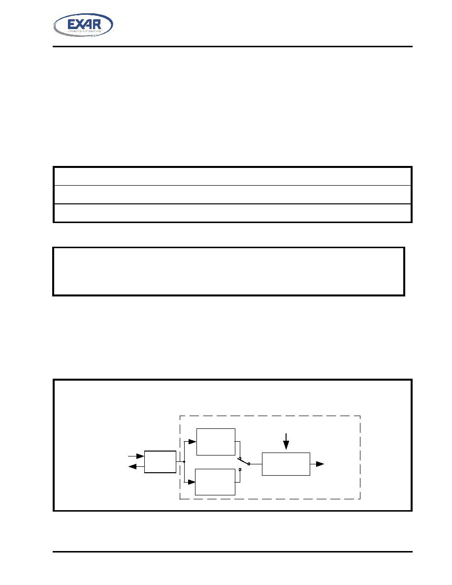
FIGURE 7. BAUD RATE GENERATOR
XTAL1
XTAL2
Crystal
Osc/
Buffer
MCR Bit-7=0
(default)
MCR Bit-7=1
DLL, DLM and DLD
Registers
Prescaler
Divide by 1
Prescaler
Divide by 4
16X or 8X or 4X
Sampling
Rate Clock
to Transmitter
and Receiver
Fractional Baud
Rate Generator
Logic
相关PDF资料 |
PDF描述 |
|---|---|
| UPM1E181MPD6TD | CAP ALUM 180UF 25V 20% RADIAL |
| AQ1051N8S-T | INDUCTOR 1.8NH 760MA 0402 SMD |
| UPS2G3R3MPD1TD | CAP ALUM 3.3UF 400V 20% RADIAL |
| XR20V2172L64-0A-EB | EVAL BOARD FOR XR20V2170 64QFN |
| UPJ1C331MPD6TD | CAP ALUM 330UF 16V 20% RADIAL |
相关代理商/技术参数 |
参数描述 |
|---|---|
| XR-210 | 制造商:EXAR 制造商全称:EXAR 功能描述:FSK MODULATOR / DEMODULATOR |
| XR-2100CJ | 制造商:未知厂家 制造商全称:未知厂家 功能描述:MODEM |
| XR-2100CP | 制造商:未知厂家 制造商全称:未知厂家 功能描述:MODEM |
| XR-2103 | 制造商:EXAR 制造商全称:EXAR 功能描述:FSK Modem Filter |
| XR-2103A | 制造商:EXAR 制造商全称:EXAR 功能描述:FSK Modem Filter |
发布紧急采购,3分钟左右您将得到回复。