参数资料
| 型号: | XRT72L71IQ |
| 厂商: | Exar Corporation |
| 文件页数: | 2/102页 |
| 文件大小: | 0K |
| 描述: | IC FRAMER DS3 ATM UNI 160PQFP |
| 产品变化通告: | XRT72Lx Series Obsolescence 02/May/2012 |
| 标准包装: | 24 |
| 控制器类型: | DS3 ATM UNI,透明通道调帧器 |
| 电源电压: | 3.3V |
| 电流 - 电源: | 120mA |
| 工作温度: | -40°C ~ 85°C |
| 安装类型: | 表面贴装 |
| 封装/外壳: | 160-BQFP |
| 供应商设备封装: | 160-PQFP(28x28) |
| 包装: | 托盘 |
第1页当前第2页第3页第4页第5页第6页第7页第8页第9页第10页第11页第12页第13页第14页第15页第16页第17页第18页第19页第20页第21页第22页第23页第24页第25页第26页第27页第28页第29页第30页第31页第32页第33页第34页第35页第36页第37页第38页第39页第40页第41页第42页第43页第44页第45页第46页第47页第48页第49页第50页第51页第52页第53页第54页第55页第56页第57页第58页第59页第60页第61页第62页第63页第64页第65页第66页第67页第68页第69页第70页第71页第72页第73页第74页第75页第76页第77页第78页第79页第80页第81页第82页第83页第84页第85页第86页第87页第88页第89页第90页第91页第92页第93页第94页第95页第96页第97页第98页第99页第100页第101页第102页
XRT72L71
á
DS3 ATM UNI/CLEAR CHANNEL FRAMER
REV. 1.1.0
6
13
D9
I/O
Bi-Directional Data bus (Microprocessor Interface Section): This pin is
inactive if the Microprocessor Interface block is configured to operate over an
8 bit data bus. Please see description for D15, pin1.
14
D8
I/O
Bi-Directional Data bus (Microprocessor Interface Section): This pin is
inactive if the Microprocessor Interface block is configured to operate over an
8 bit data bus. Please see description for D15, pin1.
15
VDD
***
Power Supply Pin
16
17
18
19
D7
D6
D5
D4
I/O
Bi-Directional Data bus (Microprocessor Interface Section):
Please see description for D15, pin 1.
20
Width16
I
Microprocessor Interface Block Data Bus Width Selector: This input pin
permits the user to configure the microprocessor interface of the UNI/Framer,
to operate over either an 8 or 16 bit wide bi-directional data bus. Tying this pin
to VDD configures the Microprocessor Interface Data Bus width to be 16 bits.
Tying this pin to GND configures the Microprocessor Interface Data Bus width
to be 8 bits.
21
D3
I/O
Bi-Directional Data bus (Microprocessor Interface Section):
Please see description for D15, pin 1.
22
EncoDis
O
Encoder (B3ZS) Disable Output pin (intended to be connected to the
XRT7300 E3/DS3/STS-1 LIU IC): This output pin is intended to be connected
to the EncoDis input pin of the XRT7300 LIU IC. The user can control the state
of this output pin by writing a “0” or “1” to Bit 3 (EncoDis) of the Line Interface
Driver Register (Address = 0x72). If the user commands this signal to toggle
“High” then it will disable the B3ZS encoder circuitry within the XRT7300 IC.
Conversely, if the user commands this output signal to toggle “Low”, then the
B3ZS Encoder circuitry, within the XRT7300 IC will be enabled.
Writing a “1” to Bit 3 of the Line Interface Driver Register (Address = 0x72) will
cause this output pin to toggle “High”. Writing a “0” to this bit-field will cause
this output pin to toggle “Low”.
NOTES:
1. The user is advised to disable the B3ZS encoder (within the XRT7300
IC) if the Transmit and Receive DS3 Framers (within the UNI) are con-
figured to operate in the B3ZS line code.
2. If the designer is not using the XRT7300 DS3/E3/STS-1 Line Trans-
mitter IC, then output pin can be used for other purposes.
23
D2
I/O
Bi-Directional Data bus (Microprocessor Interface Section):
Please see description for D15, pin1.
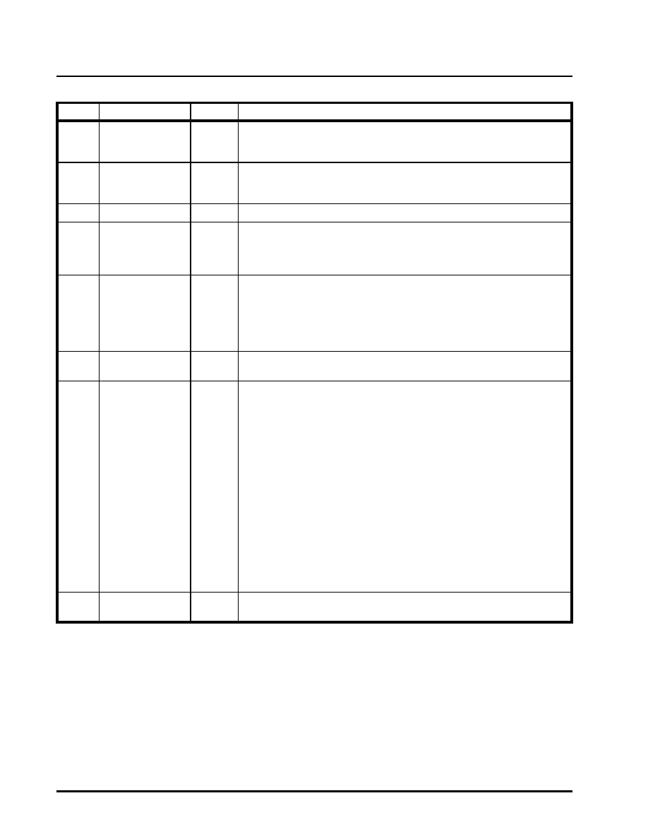
PIN DESCRIPTION (CONTINUED)
PIN NO.
SYMBOL
TYPE
DESCRIPTION
相关PDF资料 |
PDF描述 |
|---|---|
| XRT73L02MIV-F | IC LIU E3/DS3/STS-1 2CH 100TQFP |
| XRT73L03BIV-F | IC LIU E3/DS3/STS-1 3CH 120LQFP |
| XRT73L04BIV-F | IC LIU E3/DS3/STS-1 4CH 144LQFP |
| XRT73L06IB-F | IC LIU E3/DS3/STS-1 6CH 217BGA |
| XRT73LC00AIV-F | IC LIU STS1/DS3/E3 SGL 44TQFP |
相关代理商/技术参数 |
参数描述 |
|---|---|
| XRT72L71IQ-F | 功能描述:网络控制器与处理器 IC Single CH DS3 UNI (3.3V) RoHS:否 制造商:Micrel 产品:Controller Area Network (CAN) 收发器数量: 数据速率: 电源电流(最大值):595 mA 最大工作温度:+ 85 C 安装风格:SMD/SMT 封装 / 箱体:PBGA-400 封装:Tray |
| XRT72L73IB | 制造商:未知厂家 制造商全称:未知厂家 功能描述:Telecommunication IC |
| XRT72L74IB | 制造商:未知厂家 制造商全称:未知厂家 功能描述:Telecommunication IC |
| XRT7300 | 制造商:EXAR 制造商全称:EXAR 功能描述:E3/DS3/STS-1 LINE INTERFACE UNIT |
| XRT7300ES | 功能描述:网络控制器与处理器 IC RoHS:否 制造商:Micrel 产品:Controller Area Network (CAN) 收发器数量: 数据速率: 电源电流(最大值):595 mA 最大工作温度:+ 85 C 安装风格:SMD/SMT 封装 / 箱体:PBGA-400 封装:Tray |
发布紧急采购,3分钟左右您将得到回复。