- 您现在的位置:买卖IC网 > Datasheet目录307 > ADE5566ASTZF62-RL (Analog Devices Inc)IC ENERGY METERING 1PHASE 64LQFP Datasheet资料下载
参数资料
| 型号: | ADE5566ASTZF62-RL |
| 厂商: | Analog Devices Inc |
| 文件页数: | 132/156页 |
| 文件大小: | 0K |
| 描述: | IC ENERGY METERING 1PHASE 64LQFP |
| 产品变化通告: | Product Discontinuance 27/Oct/2011 |
| 标准包装: | 1,500 |
| 输入阻抗: | 770 千欧 |
| 测量误差: | 0.1% |
| 电压 - 高输入/输出: | 2V |
| 电压 - 低输入/输出: | 0.8V |
| 电源电压: | 2.4 V ~ 3.7 V |
| 测量仪表类型: | 单相 |
| 工作温度: | -40°C ~ 85°C |
| 安装类型: | 表面贴装 |
| 封装/外壳: | 64-LQFP |
| 供应商设备封装: | 64-LQFP(10x10) |
| 包装: | 带卷 (TR) |
第1页第2页第3页第4页第5页第6页第7页第8页第9页第10页第11页第12页第13页第14页第15页第16页第17页第18页第19页第20页第21页第22页第23页第24页第25页第26页第27页第28页第29页第30页第31页第32页第33页第34页第35页第36页第37页第38页第39页第40页第41页第42页第43页第44页第45页第46页第47页第48页第49页第50页第51页第52页第53页第54页第55页第56页第57页第58页第59页第60页第61页第62页第63页第64页第65页第66页第67页第68页第69页第70页第71页第72页第73页第74页第75页第76页第77页第78页第79页第80页第81页第82页第83页第84页第85页第86页第87页第88页第89页第90页第91页第92页第93页第94页第95页第96页第97页第98页第99页第100页第101页第102页第103页第104页第105页第106页第107页第108页第109页第110页第111页第112页第113页第114页第115页第116页第117页第118页第119页第120页第121页第122页第123页第124页第125页第126页第127页第128页第129页第130页第131页当前第132页第133页第134页第135页第136页第137页第138页第139页第140页第141页第142页第143页第144页第145页第146页第147页第148页第149页第150页第151页第152页第153页第154页第155页第156页
�� �
�
�ADE5166/ADE5169/ADE5566/ADE5569�
�UART� OPERATION� MODES�
�Mode� 0� (Shift� Register� with� Baud� Rate� Fixed� at� f� CORE� /12)�
�Mode� 0� is� selected� when� the� SM0� and� SM1� bits� in� the� serial�
�communications� control� SFR� (SCON,� Address� 0x98[7:6])� are�
�cleared.� In� this� shift� register� mode,� serial� data� enters� and� exits�
�through� the� RxD� pin.� The� TxD� pin� outputs� the� shift� clock.� The�
�Data� Sheet�
�Reception� is� initiated� when� a� 1-to-0� transition� is� detected� on�
�the� RxD� pin.� Assuming� that� a� valid� start� bit� is� detected,� char-�
�acter� reception� continues.� The� eight� data� bits� are� clocked� into�
�the� internal� serial� port� shift� register.�
�All� of� the� following� conditions� must� be� met� at� the� time� the� final�
�shift� pulse� is� generated� to� receive� a� character:�
�baud� rate� is� fixed� at� f� CORE� /12.� Eight� data� bits� are� transmitted� or�
�received.�
�Transmission� is� initiated� by� any� instruction� that� writes� to� the�
�serial� port� buffer� SFR� (SBUF,� Address� 0x99).� The� data� is� shifted�
�out� of� the� Pin� RxD� line.� The� eight� bits� are� transmitted� with� the�
�least� significant� bit� (LSB)� first.�
�Reception� is� initiated� when� the� serial� port� receive� enable� bit,�
�REN� (SCON[4]),� is� 1,� and� the� serial� port� receive� interrupt� bit,� RI�
�?�
�?�
�If� the� extended� UART� is� disabled� (EXTEN� =� 0� in� the� CFG�
�SFR,� Address� 0xAF[6]),� RI� (SCON[0])� must� be� 0� to� receive�
�a� character.� This� ensures� that� the� data� in� the� SBUF� SFR� is� not�
�overwritten� if� the� last� received� character� has� not� been� read.�
�If� frame� error� checking� is� enabled� by� setting� SM2� (SCON[5]),�
�the� received� stop� bit� must� be� set� to� receive� a� character.� This�
�ensures� that� every� character� received� comes� from� a� valid�
�frame,� with� both� a� start� bit� and� a� stop� bit.�
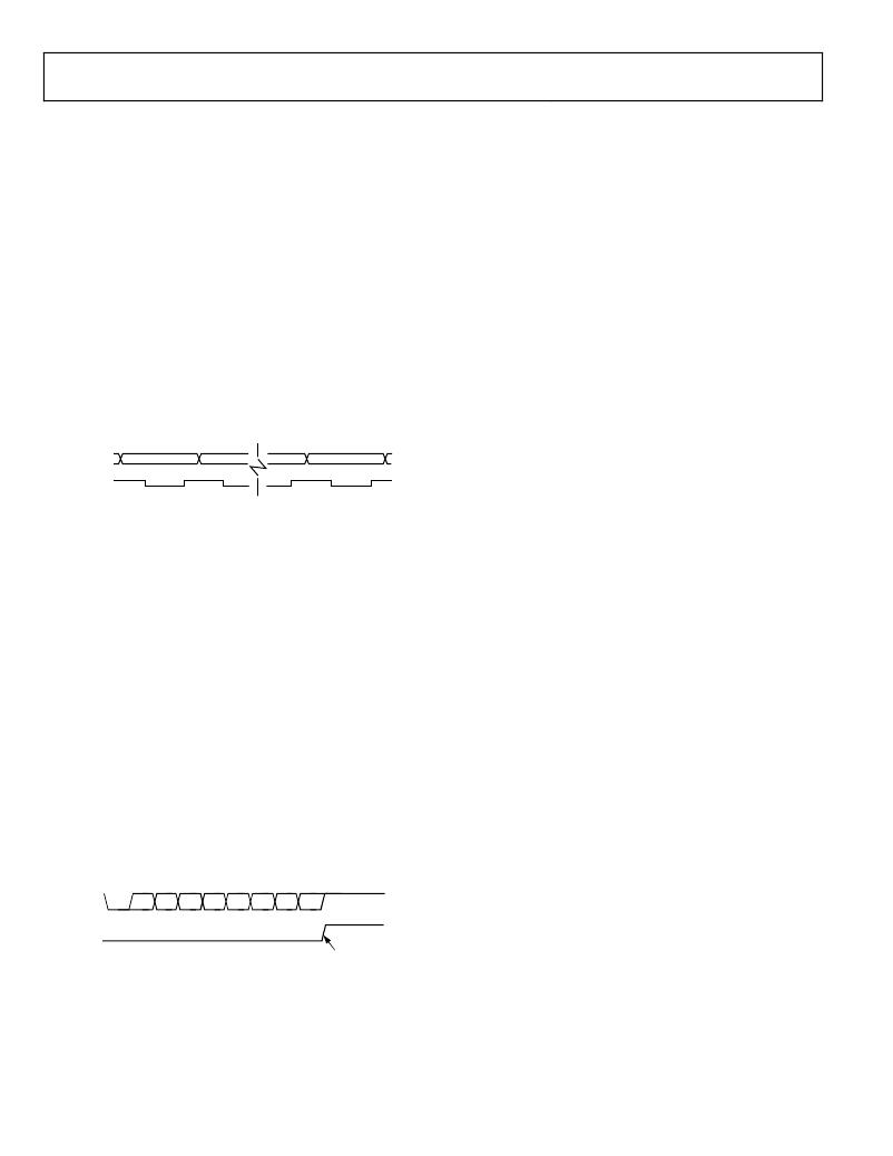
�(SCON[0]),� is� 0.� When� RI� is� cleared,� the� data� is� clocked� into� the�
�Pin� RxD� line,� and� the� clock� pulses� are� output� from� the� Pin� TxD�
�line� as� shown� in� Figure� 105.�
�If� any� of� these� conditions� is� not� met,� the� received� frame� is� irre-�
�trievably� lost,� and� the� receive� interrupt� flag� (RI,� SCON[0])� is�
�not� set.�
�RxD�
�(DATA� OUT)�
�TxD�
�DATA� BIT� 0�
�DATA� BIT� 1�
�DATA� BIT� 6�
�DATA� BIT� 7�
�If� the� received� frame� meets� these� conditions,� the� following�
�events� occur:�
�(SHIFT� CLOCK)�
�Figure� 105.� 8-Bit� Shift� Register� Mode�
�?�
�The� eight� bits� in� the� receive� shift� register� are� latched� into�
�the� SBUF� SFR.�
�Mode� 1� (8-Bit� UART� with� Variable� Baud� Rate)�
�Mode� 1� is� selected� by� clearing� the� SM0� bit� (SCON[7])� and� setting�
�?�
�?�
�The� ninth� bit� (stop� bit)� is� clocked� into� RB8� (SCON[2]).�
�The� receiver� interrupt� flag� (RI,� SCON[0])� is� set.�
�the� SM1� bit� (SCON[6]).� Each� data� byte� (LSB� first)� is� preceded� by�
�a� start� bit� (0)� and� followed� by� a� stop� bit� (1).� Therefore,� each� frame�
�consists� of� 10� bits� transmitted� on� the� TxD� pin� or� received� on� the�
�RxD� pin.�
�The� baud� rate� is� set� by� a� timer� overflow� rate.� Timer� 1� or� Timer� 2�
�can� be� used� to� generate� baud� rates,� or� both� timers� can� be� used�
�simultaneously� where� one� generates� the� transmit� rate� and� the�
�other� generates� the� receive� rate.� There� is� also� a� dedicated� timer�
�for� baud� rate� generation,� the� UART� timer,� which� has� a� fractional�
�divisor� to� precisely� generate� any� baud� rate� (see� the� UART� Timer�
�Generated� Baud� Rates� section).�
�Transmission� is� initiated� by� a� write� to� the� serial� port� buffer� SFR�
�(SBUF,� Address� 0x99).� Next,� a� stop� bit� (1)� is� loaded� into� the� ninth�
�bit� position� of� the� internal� serial� port� shift� register.� The� data� is�
�output� bit� by� bit� until� the� stop� bit� appears� on� the� TxD� pin� and�
�the� transmit� interrupt� flag,� TI� (Address� 0x98[1]),� is� automati-�
�cally� set,� as� shown� in� Figure� 106.�
�Mode� 2� (9-Bit� UART� with� Baud� Rate� Fixed� at� f� CORE� /64� or�
�f� CORE� /32)�
�Mode� 2� is� selected� by� setting� SM0� and� clearing� SM1.� In� this� mode,�
�the� UART� operates� in� 9-bit� mode� with� a� fixed� baud� rate.� The�
�baud� rate� is� fixed� at� f� CORE� /64� by� default,� although� setting� the� SMOD�
�bit� in� the� program� control� SFR� (PCON,� Address� 0x87[7])� doubles�
�the� frequency� to� f� CORE� /32.� Eleven� bits� are� transmitted� or� received:�
�a� start� bit� (0),� eight� data� bits,� a� programmable� ninth� bit,� and� a� stop�
�bit� (1).� The� ninth� bit� is� most� often� used� as� a� parity� bit� or� as� part�
�of� a� multiprocessor� communication� protocol,� although� it� can� be�
�used� for� anything,� including� a� ninth� data� bit,� if� required.�
�To� use� the� ninth� data� bit� as� part� of� a� communication� protocol� for�
�a� multiprocessor� network� such� as� RS-485,� the� ninth� bit� is� set� to�
�indicate� that� the� frame� contains� the� address� of� the� device� with�
�which� the� master� wants� to� communicate.� The� devices� on� the� net-�
�work� are� always� listening� for� a� packet� with� the� ninth� bit� set� and�
�are� configured� such� that� if� the� ninth� bit� is� cleared,� the� frame� is� not�
�TxD�
�START�
�BIT�
�D0�
�D1�
�D2�
�D3�
�D4�
�D5�
�D6�
�D7�
�STOP� BIT�
�valid,� and� a� receive� interrupt� is� not� generated.� If� the� ninth� bit� is� set,�
�all� devices� on� the� network� receive� the� address� and� obtain� a� receive�
�TI�
�(SCON[1])�
�SET� INTERRUPT�
�(FOR� EXAMPLE,�
�READY� FOR� MORE� DATA)�
�Figure� 106.� 8-Bit� Variable� Baud� Rate�
�character� interrupt.� The� devices� examine� the� address� and,� if� it�
�matches� one� of� the� preprogrammed� addresses� of� the� device,� that�
�device� configures� itself� to� listen� to� all� incoming� frames,� even� those�
�with� the� ninth� bit� cleared.� Because� the� master� has� initiated� commu-�
�nication� with� that� device,� all� the� following� packets� with� the� ninth�
�bit� cleared� are� intended� specifically� for� that� addressed� device� until�
�another� packet� with� the� ninth� bit� set� is� received.� If� the� address�
�does� not� match,� the� device� continues� to� listen� for� address� packets.�
�Rev.� D� |� Page� 132� of� 156�
�相关PDF资料 |
PDF描述 |
|---|---|
| ADE7156ASTZF16 | IC ENERGY METER 64-LQFP |
| ADE7156ASTZF8-RL | IC ENERGY METER 64-LQFP |
| ADE7518ASTZF8-RL | IC ENERGY METER MCU 8K 64LQFP |
| ADE7569ASTZF16 | IC ENERGY METER MCU 16K 64LQFP |
| ADE7752BARWZ-RL | IC ENERGY METERING 3PHASE 24SOIC |
相关代理商/技术参数 |
参数描述 |
|---|---|
| ADE5569 | 制造商:AD 制造商全称:Analog Devices 功能描述:Single-Phase Energy Measurement IC with 8052 MCU, RTC, and LCD Driver |
| ADE5569ASTZF62 | 功能描述:IC METER/8052/RTC/LCD DRV 64LQFP RoHS:是 类别:集成电路 (IC) >> PMIC - 能量测量 系列:- 产品培训模块:Lead (SnPb) Finish for COTS Obsolescence Mitigation Program 标准包装:2,500 系列:* |
| ADE5569ASTZF62 | 制造商:Analog Devices 功能描述:Energy Management IC |
| ADE5569ASTZF62-RL | 功能描述:IC METER/8052/RTC/LCD DRV 64LQFP RoHS:是 类别:集成电路 (IC) >> PMIC - 能量测量 系列:- 产品培训模块:Lead (SnPb) Finish for COTS Obsolescence Mitigation Program 标准包装:2,500 系列:* |
| ADE-6 | 制造商:MINI 制造商全称:Mini-Circuits 功能描述:Surface Mount Frequency Mixer |
发布紧急采购,3分钟左右您将得到回复。