- 您现在的位置:买卖IC网 > Datasheet目录307 > ADE5566ASTZF62-RL (Analog Devices Inc)IC ENERGY METERING 1PHASE 64LQFP Datasheet资料下载
参数资料
| 型号: | ADE5566ASTZF62-RL |
| 厂商: | Analog Devices Inc |
| 文件页数: | 65/156页 |
| 文件大小: | 0K |
| 描述: | IC ENERGY METERING 1PHASE 64LQFP |
| 产品变化通告: | Product Discontinuance 27/Oct/2011 |
| 标准包装: | 1,500 |
| 输入阻抗: | 770 千欧 |
| 测量误差: | 0.1% |
| 电压 - 高输入/输出: | 2V |
| 电压 - 低输入/输出: | 0.8V |
| 电源电压: | 2.4 V ~ 3.7 V |
| 测量仪表类型: | 单相 |
| 工作温度: | -40°C ~ 85°C |
| 安装类型: | 表面贴装 |
| 封装/外壳: | 64-LQFP |
| 供应商设备封装: | 64-LQFP(10x10) |
| 包装: | 带卷 (TR) |
第1页第2页第3页第4页第5页第6页第7页第8页第9页第10页第11页第12页第13页第14页第15页第16页第17页第18页第19页第20页第21页第22页第23页第24页第25页第26页第27页第28页第29页第30页第31页第32页第33页第34页第35页第36页第37页第38页第39页第40页第41页第42页第43页第44页第45页第46页第47页第48页第49页第50页第51页第52页第53页第54页第55页第56页第57页第58页第59页第60页第61页第62页第63页第64页当前第65页第66页第67页第68页第69页第70页第71页第72页第73页第74页第75页第76页第77页第78页第79页第80页第81页第82页第83页第84页第85页第86页第87页第88页第89页第90页第91页第92页第93页第94页第95页第96页第97页第98页第99页第100页第101页第102页第103页第104页第105页第106页第107页第108页第109页第110页第111页第112页第113页第114页第115页第116页第117页第118页第119页第120页第121页第122页第123页第124页第125页第126页第127页第128页第129页第130页第131页第132页第133页第134页第135页第136页第137页第138页第139页第140页第141页第142页第143页第144页第145页第146页第147页第148页第149页第150页第151页第152页第153页第154页第155页第156页
�� �
�
�Data� Sheet�
�ADE5166/ADE5169/ADE5566/ADE5569�
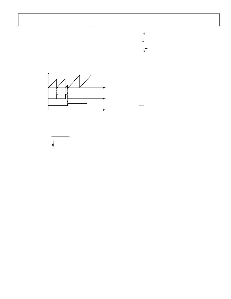
�When� a� new� half-line� cycle� is� written� in� the� LINCYC� register�
�(Address� 0x12),� the� LWATTHR� register� (Address� 0x03)� is� reset,�
�and� a� new� accumulation� starts� at� the� next� zero� crossing.� The�
�V� (� t� )� =� 2� ×� V� sin(� ω� t� +� θ� )�
�I� (� t� )� =� 2� ×� I� sin(� ω� t� )�
�(19)�
�I� '� (� t� )� =� 2� ×� I� sin� ?� ?� ω� t� +�
�π� ?�
�2� ?�
�number� of� half-line� cycles� is� then� counted� until� LINCYC� is�
�reached.� This� implementation� provides� a� valid� measurement� at�
�the� first� CYCEND� interrupt� after� writing� to� the� LINCYC� register�
�?�
�?�
�(20)�
�(see� Figure� 71).� The� line� active� energy� accumulation� uses� the�
�same� signal� path� as� the� active� energy� accumulation.� The� LSB�
�size� of� these� two� registers� is� equivalent.�
�where:�
�θ� is� the� phase� difference� between� the� voltage� and� current� channel.�
�V� is� the� rms� voltage.�
�I� is� the� rms� current.�
�q� (� t� )� =� V� (� t� )� ×� I� ’(� t� )�
�(21)�
�LWATTHR� REGISTER�
�CYCEND� IRQ�
�q� (� t� )� =� VI� sin� (θ)� +� VI� sin(2ω� t� +� θ)�
�The� average� reactive� power� over� an� integral� number� of� lines� (n)�
�is� given� in� Equation� 22.�
�LINCYC�
�VALUE�
�Q� =�
�1�
�nT�
�nT�
�∫� q� (� t� )� dt� =� VI� sin(� θ� )�
�0�
�(22)�
�?� ?� nT�
�VI�
�cos� (� 2� π� ft� )� dt�
�?� 1� +� ?�
�?� 8� .� 9� ?� ?�
�Figure� 71.� Energy� Accumulation� When� LINCYC� Changes�
�Using� the� information� from� Equation� 8� and� Equation� 9�
�?� ?�
�?� ?�
�nT�
�E� (� t� )� =� ∫� VI� dt� ?� ?� 2� ?� ∫�
�0� ?� ?� f� ?� ?� 0�
�?� ?�
�?�
�where:�
�n� is� an� integer.�
�T� is� the� line� cycle� period.�
�(16)�
�where:�
�T� is� the� line� cycle� period.�
�q� is� referred� to� as� the� reactive� power.�
�Note� that� the� reactive� power� is� equal� to� the� dc� component� of�
�the� instantaneous� reactive� power� signal,� q(t),� in� Equation� 21.�
�The� instantaneous� reactive� power� signal,� q(t),� is� generated� by�
�multiplying� the� voltage� and� current� channels.� In� this� case,� the�
�phase� of� the� current� channel� is� shifted� by� 90°.� The� dc� component� of�
�the� instantaneous� reactive� power� signal� is� then� extracted� by� a�
�low-pass� filter� to� obtain� the� reactive� power� information� (see�
�Figure� 72).�
�Because� the� sinusoidal� component� is� integrated� over� an� integer�
�number� of� line� cycles,� its� value� is� always� 0.� Therefore,�
�In� addition,� the� phase-shifting� filter� has� a� nonunity� magnitude�
�response.� Because� the� phase-shifted� filter� has� a� large� attenuation�
�nT�
�E� =� ∫� VIdt� +� 0�
�0�
�E� (� t� )� =� VInT�
�(17)�
�(18)�
�at� high� frequency,� the� reactive� power� is� primarily� for� calculation�
�at� line� frequency.� The� effect� of� harmonics� is� largely� ignored� in�
�the� reactive� power� calculation.� Note� that,� because� of� the� magnitude�
�characteristic� of� the� phase� shifting� filter,� the� weight� of� the� reactive�
�Note� that� in� this� mode,� the� 16-bit� LINCYC� register� can� hold�
�a� maximum� value� of� 65,535.� In� other� words,� the� line� energy�
�accumulation� mode� can� be� used� to� accumulate� active� energy�
�for� a� maximum� duration� of� 65,535� half-line� cycles.� At� a� 60� Hz�
�line� frequency,� the� total� duration� of� 65,535/120� Hz� =� 546� sec.�
�REACTIVE� POWER� CALCULATION�
�(ADE5169/ADE5569� ONLY)�
�Reactive� power,� a� function� available� for� the� ADE5169/ADE5569,�
�is� defined� as� the� product� of� the� voltage� and� current� waveforms�
�when� one� of� these� signals� is� phase-shifted� by� 90°.� The� resulting�
�waveform� is� called� the� instantaneous� reactive� power� signal.�
�Equation� 21� gives� an� expression� for� the� instantaneous� reactive�
�power� signal� in� an� ac� system� when� the� phase� of� the� current�
�channel� is� shifted� by� 90°.�
�power� is� slightly� different� from� the� active� power� calculation�
�(see� the� Energy� Register� Scaling� section).�
�The� frequency� response� of� the� LPF� in� the� reactive� signal� path� is�
�identical� to� the� one� used� for� LPF2� in� the� average� active� power�
�calculation.� Because� LPF2� does� not� have� an� ideal� brick� wall�
�frequency� response� (see� Figure� 65),� the� reactive� power� signal�
�has� some� ripple� due� to� the� instantaneous� reactive� power� signal.�
�This� ripple� is� sinusoidal� and� has� a� frequency� equal� to� 2� the�
�line� frequency.� Because� the� ripple� is� sinusoidal� in� nature,� it� is�
�removed� when� the� reactive� power� signal� is� integrated� to�
�calculate� energy.�
�The� reactive� power� signal� can� be� read� from� the� waveform� register�
�by� setting� the� WAVMODE� register� (Address� 0x0D)� and� the�
�WFSM� bit� (Bit� 5)� in� the� Interrupt� Enable� 3� SFR� (MIRQENH,�
�Address� 0xDB).� Like� the� current� and� voltage� channels� waveform�
�sampling� modes,� the� waveform� data� is� available� at� sample� rates�
�of� 25.6� kSPS,� 12.8� kSPS,� 6.4� kSPS,� and� 3.2� kSPS.�
�Rev.� D� |� Page� 65� of� 156�
�相关PDF资料 |
PDF描述 |
|---|---|
| ADE7156ASTZF16 | IC ENERGY METER 64-LQFP |
| ADE7156ASTZF8-RL | IC ENERGY METER 64-LQFP |
| ADE7518ASTZF8-RL | IC ENERGY METER MCU 8K 64LQFP |
| ADE7569ASTZF16 | IC ENERGY METER MCU 16K 64LQFP |
| ADE7752BARWZ-RL | IC ENERGY METERING 3PHASE 24SOIC |
相关代理商/技术参数 |
参数描述 |
|---|---|
| ADE5569 | 制造商:AD 制造商全称:Analog Devices 功能描述:Single-Phase Energy Measurement IC with 8052 MCU, RTC, and LCD Driver |
| ADE5569ASTZF62 | 功能描述:IC METER/8052/RTC/LCD DRV 64LQFP RoHS:是 类别:集成电路 (IC) >> PMIC - 能量测量 系列:- 产品培训模块:Lead (SnPb) Finish for COTS Obsolescence Mitigation Program 标准包装:2,500 系列:* |
| ADE5569ASTZF62 | 制造商:Analog Devices 功能描述:Energy Management IC |
| ADE5569ASTZF62-RL | 功能描述:IC METER/8052/RTC/LCD DRV 64LQFP RoHS:是 类别:集成电路 (IC) >> PMIC - 能量测量 系列:- 产品培训模块:Lead (SnPb) Finish for COTS Obsolescence Mitigation Program 标准包装:2,500 系列:* |
| ADE-6 | 制造商:MINI 制造商全称:Mini-Circuits 功能描述:Surface Mount Frequency Mixer |
发布紧急采购,3分钟左右您将得到回复。