- 您现在的位置:买卖IC网 > PDF目录298893 > BX80552661 (INTEL CORP) 32-BIT, 3600 MHz, MICROPROCESSOR, PBGA775 PDF资料下载
参数资料
| 型号: | BX80552661 |
| 厂商: | INTEL CORP |
| 元件分类: | 微控制器/微处理器 |
| 英文描述: | 32-BIT, 3600 MHz, MICROPROCESSOR, PBGA775 |
| 封装: | FLIP CHIP, LGA-775 |
| 文件页数: | 103/108页 |
| 文件大小: | 3283K |
| 代理商: | BX80552661 |
第1页第2页第3页第4页第5页第6页第7页第8页第9页第10页第11页第12页第13页第14页第15页第16页第17页第18页第19页第20页第21页第22页第23页第24页第25页第26页第27页第28页第29页第30页第31页第32页第33页第34页第35页第36页第37页第38页第39页第40页第41页第42页第43页第44页第45页第46页第47页第48页第49页第50页第51页第52页第53页第54页第55页第56页第57页第58页第59页第60页第61页第62页第63页第64页第65页第66页第67页第68页第69页第70页第71页第72页第73页第74页第75页第76页第77页第78页第79页第80页第81页第82页第83页第84页第85页第86页第87页第88页第89页第90页第91页第92页第93页第94页第95页第96页第97页第98页第99页第100页第101页第102页当前第103页第104页第105页第106页第107页第108页
96
Datasheet
Boxed Processor Specifications
The fan heatsink receives a PWM signal from the motherboard from the fourth pin of the connector
labeled as CONTROL.
Note:
The boxed processor’s fan heatsink requires a constant +12 V supplied to pin 2 and does not
support variable voltage control or 3-pin PWM control.
The power header on the baseboard must be positioned to allow the fan heatsink power cable to
reach it. The power header identification and location should be documented in the platform
documentation, or on the system board itself. Figure 7-6 shows the location of the fan power
connector relative to the processor socket. The baseboard power header should be positioned
within 4.33 inches from the center of the processor socket.
NOTE:
1. Baseboard should pull this pin up to 5 V with a resistor.
2. Open Drain Type, Pulse Width Modulated.
3. Fan will have a pull-up resistor to 4.75 V, maximum 5.25 V.
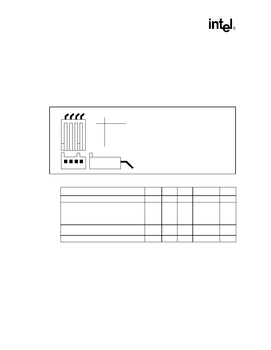
Figure 7-5. Boxed Processor Fan Heatsink Power Cable Connector Description
Table 7-1. Fan Heatsink Power and Signal Specifications
Description
Min
Typ
Max
Unit
Notes
+12 V: 12 volt fan power supply
10.2
12
13.8
V
-
IC:
Peak Fan current draw
Fan start-up current draw
Fan start-up current draw maximum duration
—
1.1
—
1.5
2.2
1.0
A
Second
-
SENSE: SENSE frequency
—
2
—
pulses per fan
revolution
1
CONTROL
21
25
28
kHz
2,3
Pin
Signal
12 34
1
2
3
4
GND
+12 V
SENSE
CONTROL
Straight square pin, 4-pin terminal housing with
polarizing ribs and friction locking ramp.
0.100" pitch, 0.025" square pin width.
Match with straight pin, friction lock header on
mainboard.
相关PDF资料 |
PDF描述 |
|---|---|
| BX80552651T2 | 32-BIT, 3400 MHz, MICROPROCESSOR, PBGA775 |
| BX80552641T | 32-BIT, 3200 MHz, MICROPROCESSOR, PBGA775 |
| BX80552641T2 | 32-BIT, 3200 MHz, MICROPROCESSOR, PBGA775 |
| BX805555060P | 64-BIT, MICROPROCESSOR, BGA771 |
| BX805555080P | 64-BIT, MICROPROCESSOR, BGA771 |
相关代理商/技术参数 |
参数描述 |
|---|---|
| BX80552661T2 | 制造商:Intel 功能描述:P4 661 3.6GHZ LP-BTX 2MB - Boxed Product (Development Kits) |
| BX80553915 S L9KB | 制造商:Intel 功能描述: |
| BX80553915R S L9DA | 制造商:Intel 功能描述: |
| BX80553925 S L9KA | 制造商:Intel 功能描述: |
| BX80553945 S L9QQ | 制造商:Intel 功能描述:PENTIUM D PROCESSOR 945 |
发布紧急采购,3分钟左右您将得到回复。