- 您现在的位置:买卖IC网 > PDF目录298899 > CA95C09-10CT TELECOM, DATA ENCRYPTION CIRCUIT, PQFP44 PDF资料下载
参数资料
| 型号: | CA95C09-10CT |
| 元件分类: | 加密电路 |
| 英文描述: | TELECOM, DATA ENCRYPTION CIRCUIT, PQFP44 |
| 封装: | TQFP-44 |
| 文件页数: | 40/42页 |
| 文件大小: | 180K |
| 代理商: | CA95C09-10CT |
第1页第2页第3页第4页第5页第6页第7页第8页第9页第10页第11页第12页第13页第14页第15页第16页第17页第18页第19页第20页第21页第22页第23页第24页第25页第26页第27页第28页第29页第30页第31页第32页第33页第34页第35页第36页第37页第38页第39页当前第40页第41页第42页
Tundra Semiconductor Corporation
CA95C68/18/09
Tundra Semiconductor Corporation
3-31
30
33
27
I
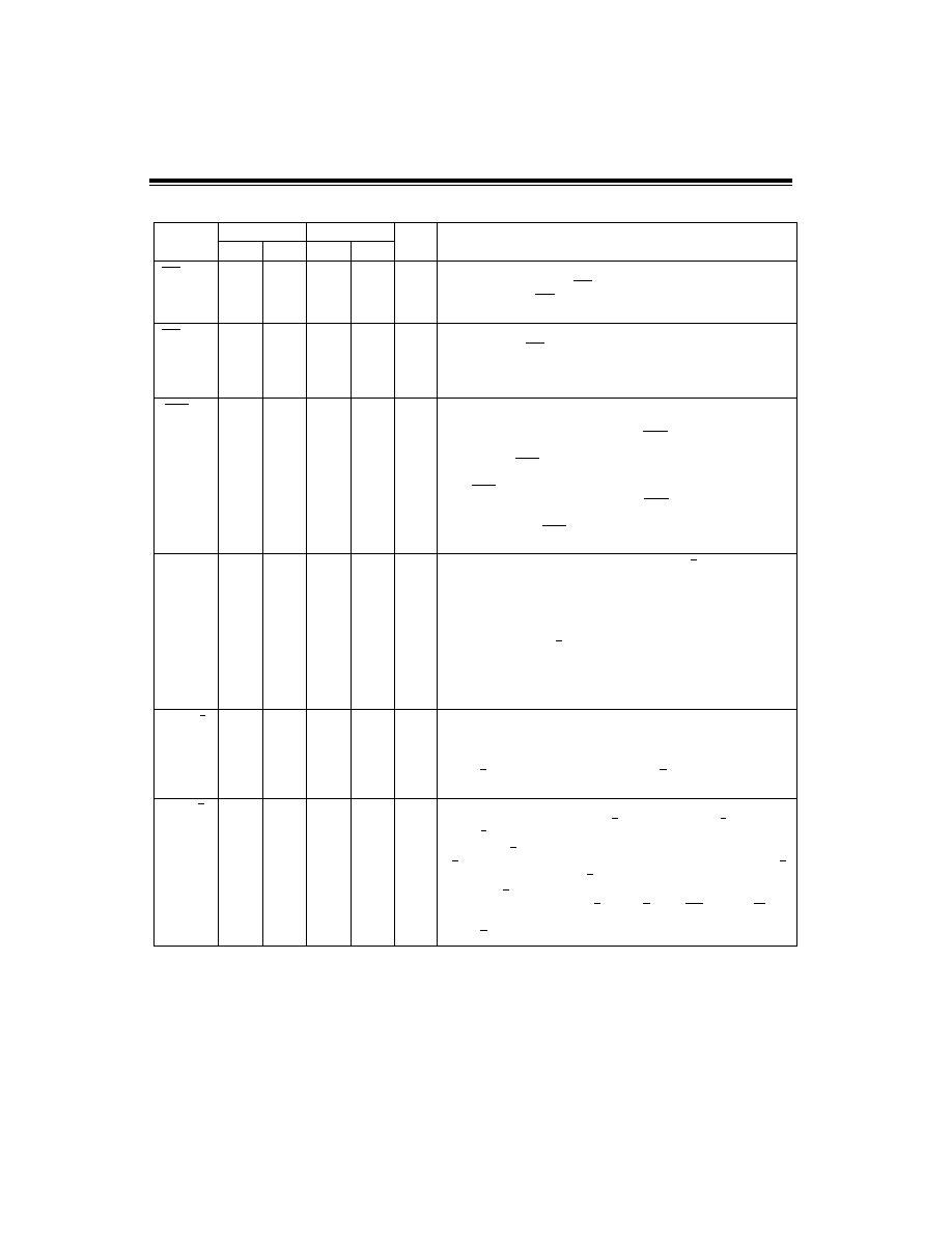
Slave Port Chip Select: This active LOW signal is logically combined with
the Slave Port Data Strobe (
) to facilitate Slave Port data transfers in a
bus environment.
is not latched internally, and may be tied
permanently LOW without impairing Slave Port operation.
29
32
26
I
Slave Port Data Strobe: This active LOW input, in conjunction with Slave
Port Chip Select (
) LOW indicates to the DCP that valid data is on the
SP7-SP0 lines for an input operation, or that data is to be driven onto SP7-
SP0 lines for output. The direction of data ow is determined by Control bits
in the Mode Register. (See Register Description).
31
34
35
29
O
Slave Port Flag: This active LOW output indicates the state of either the
Input Register or the Output Register, depending on the Mode Register
conguration. In single port conguration,
will go active whenever
the Output Register is not empty during normal processing. In dual port
conguration,
will reect the content of whichever register is
associated with the Slave Port. If the Input Register is assigned to the Slave
Port,
will go active whenever the Input Register is not full, once any
of the Start commands has been entered;
will be forced inactive if
any other command is entered. Conversely, if the Slave Port is assigned to
the Output Register,
will go active whenever the Output Register is
not empty.
AUX7-AUX0
32-35
9-6
36-39
10-7
36-39
10-7
30-33
4-1
I/O
Auxiliary Port Bus: In Multiplexed Control Mode (C/K LOW), these eight
lines form a key byte input port which may be used to enter the Master and
Session Keys. The Master Key can only be entered through this port but
Session Keys may alternatively be entered via the Master Port. AUX0 is the
low-order bit, and is considered to be the Parity bit in key bytes. The most
signicant byte of the key is entered rst. When the DCP is operated in
Direct Control Mode, (C/K HIGH), the Auxiliary Port's key-entry function is
disabled and ve of the eight lines become direct control/status lines for
interfacing to high-speed microprogrammed controllers. In this case, AUX0,
AUX1 and AUX4 have no function (they may be tied HIGH) and the other pins
are dened on the following pages.
AUX5 –S/S
34
38
32
I
Start/Stop: In Direct Control Mode, when this pin goes LOW (Stop) the DCP
will follow the sequence that would normally occur when a Stop Command is
entered. Conversely, when this input goes HIGH, a sequence equivalent to a
Start Encryption or Start Decryption command will be followed. At the time
AUX5-S/S goes HIGH, the level on AUX6-E/D selects either the Start
Encryption or Start Decryption ciphering operation.
AUX6 –E/D
33
37
31
I
Encrypt/Decrypt: In Direct Control Mode, this input species whether the
ciphering algorithm is to encrypt (E/D HIGH) or decrypt (E/D LOW) when
AUX5-S/S goes HIGH to initiate a normal data ciphering operation.
When AUX7-K/D goes HIGH, initiating entry of key bytes, the level on AUX6-
E/D species whether the bytes are to be written into the E Key Register (E/D
HIGH) or the D Key Register (E/D LOW).
The AUX6-E/D input is not latched internally, and must be held constant
whenever one or more of AUX5-S/S, AUX7-K/D, AUX2-
, or AUX3-
are
active. Corrupted data in the internal registers will occur if the proper level on
AUX6-E/D is not maintained during loading or ciphering operations.
Table 3-2 : Pin Description Cont'd
Symbol
95C68/18
95C09
TYPE
Name and Function
PDIP
PLCC
TQFP
SCS
SDS
SCS
SDS
SCS
SFLG
BSY
CP
相关PDF资料 |
PDF描述 |
|---|---|
| CA95C09-16CT | TELECOM, DATA ENCRYPTION CIRCUIT, PQFP44 |
| CA95C09-20CT | TELECOM, DATA ENCRYPTION CIRCUIT, PQFP44 |
| CA95C09-25CT | TELECOM, DATA ENCRYPTION CIRCUIT, PQFP44 |
| CA95C09-33CT | TELECOM, DATA ENCRYPTION CIRCUIT, PQFP44 |
| CA95C09-5CT | TELECOM, DATA ENCRYPTION CIRCUIT, PQFP44 |
相关代理商/技术参数 |
参数描述 |
|---|---|
| CA96 | 制造商:Datak Corporation 功能描述: |
| CA9623-000 | 功能描述:CABLE RoHS:是 类别:线缆,导线 >> 同轴 系列:- 产品培训模块:General Cable 标准包装:1 系列:- 缆线类型:细电缆网 - 耐热阻燃型 缆线组:RG-58 线规:20 AWG(0.62mm²) 线束:19 股 / 32 AWG 套管类型:聚氯乙烯(PVC) 套管直径:0.186"(4.72mm) 屏蔽类型:箔,编织线 阻抗:50 欧姆 长度:100' (30.5m) 颜色:灰 使用:网络 特点:- 导线材料:铜,镀锡 电介质材料:多孔(泡沫)聚乙烯(多孔 FPE) 电介质直径:0.100"(2.54mm) 屏蔽材料:Flexfoil?; 铜,镀锡 屏蔽覆盖范围:100%,81% VoP,传输速度:80 工作温度:- 其它名称:C5779-100 |
| CA9652-000 | 制造商:TE Connectivity 功能描述:- Bulk |
| CA9681-000 | 制造商:TE Connectivity 功能描述:CA9681-000 |
| CA9809-000 | 制造商:TE Connectivity 功能描述:Heat Shrink Molded Boot 制造商:TE Connectivity 功能描述:222K142-25-CS-2101-0 - Bulk |
发布紧急采购,3分钟左右您将得到回复。