- 您现在的位置:买卖IC网 > PDF目录171067 > DDP3315CQA (MICRONAS SEMICONDUCTOR HOLDING AG) SPECIALTY CONSUMER CIRCUIT, PQFP80 PDF资料下载
参数资料
| 型号: | DDP3315CQA |
| 厂商: | MICRONAS SEMICONDUCTOR HOLDING AG |
| 元件分类: | 消费家电 |
| 英文描述: | SPECIALTY CONSUMER CIRCUIT, PQFP80 |
| 封装: | PLASTIC, QFP-80 |
| 文件页数: | 15/62页 |
| 文件大小: | 1746K |
| 代理商: | DDP3315CQA |
第1页第2页第3页第4页第5页第6页第7页第8页第9页第10页第11页第12页第13页第14页当前第15页第16页第17页第18页第19页第20页第21页第22页第23页第24页第25页第26页第27页第28页第29页第30页第31页第32页第33页第34页第35页第36页第37页第38页第39页第40页第41页第42页第43页第44页第45页第46页第47页第48页第49页第50页第51页第52页第53页第54页第55页第56页第57页第58页第59页第60页第61页第62页
ADVANCE INFORMATION
22
Micronas
3. Serial Interface
3.1. I2C-Bus Interface
Communication between the DDP 3315C and the
external
controller
is
done
via
I2C-bus.
The
DDP 3315C has an I2C-bus slave interface and uses
I2C clock synchronization to slow down the interface if
required.
Basically there are two classes of registers in the
DDP 3315C.
The first class are directly addressable I2C registers.
They are embedded in the hardware. These registers
are 8 or 16 bits wide.
The second class are “XDFP-REGISTERS”, which are
used by the “XDFP” onchip controller. These registers
are all 16 bits wide and support read/write operation.
Communication with these registers requires I2C pack-
ets with a 16 bit XDFP-register address and 16 bit
data.
Communication with both classes of registers (I2C and
XDFP-REGISTERS) are performed via I2C. The for-
mat of the I2C telegram depends on which type of reg-
ister is being accessed.
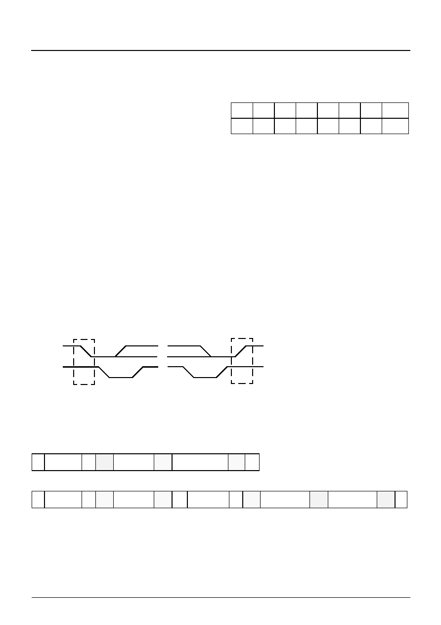
The I2C-bus chip address of the DDP 3315C is given
below:
Note: The I2C address is subject to change.
3.2. I2C Control and Status Registers
The I2C-bus interface uses one level of subaddress.
First the bus address selects the IC, then a subad-
dress selects one of the internal registers. They have 8
or 16-bit data size; 16-bit registers are accessed by
reading/writing two 8-bit data words. Writing is done by
sending the device address first followed by the sub-
address byte and one or two data bytes. For reading,
the read address has to be transmitted first by sending
the device write address followed by the subaddress a
second start condition with the device read address
and reading one or two bytes of data. Fig. 3–2 shows
I2C protocol for read and write operations; the read
operation requires an extra start condition and repeti-
tion of the chip address with read command set. Table
isters.
Fig. 3–1: I2C-Bus protocol (MSB first, data must be stable while clock is high)
Fig. 3–2: I2C-Bus protocol
A6
A5
A4
A3
A2
A1
A0
R/W
1000
1011/0
SDA
SCL
1
0
S
P
I2C-Bus Start Condition
I2C-Bus Stop Condition
S
P
=
Nak
Ack
S
1000 101 W Ack
sub-addr.
Ack S
1000 101
Ack
R
high byte data
low byte data
1 or 2 byte data
S
1000 101 W Ack sub-addr.
Ack
Ack P
P
Write to I2C control register :
Read from I2C control register :
Start condition
Stop condition
W
R
Ack
Nak
S
P
=
1 (Read bit)
0 (Write bit)
=
0 (Acknowledge bit from DDP = grey
1 (Not acknowledge bit from Controller = hatched
or Controller = hatched)
indicating an error state from DDP = grey)
or
相关PDF资料 |
PDF描述 |
|---|---|
| DDQ24W7P043A00LF | 24 CONTACT(S), MALE, D SUBMINIATURE CONNECTOR, SOLDER |
| DDQ24W7PA00LF | 24 CONTACT(S), MALE, D SUBMINIATURE CONNECTOR, SOLDER |
| DDQ36W4P043A00LF | 36 CONTACT(S), MALE, D SUBMINIATURE CONNECTOR, SOLDER |
| DDQ36W4PA00LF | 36 CONTACT(S), MALE, D SUBMINIATURE CONNECTOR, SOLDER |
| DDQ47W1P043A00LF | 47 CONTACT(S), MALE, D SUBMINIATURE CONNECTOR, SOLDER |
相关代理商/技术参数 |
参数描述 |
|---|---|
| DDP-37CT | 制造商:Pan Pacific 功能描述: |
| DDP400-P1 | 制造商:CCM Assembly & Manufacturing 功能描述:AC Input Cable for ROAL DDP400 series, Bulk |
| DDP400-P4 | 制造商:CCM Assembly & Manufacturing 功能描述:DC Output Cable for ROAL DDP400 series, Bulk |
| DDP400-P6 | 制造商:CCM Assembly & Manufacturing 功能描述:Signal Cable for ROAL DDP400 series, Bulk |
| DDP400-US12-FF | 制造商:ROAL Electronics 功能描述:AC/DC 400W 12V Single Output Enclosed Front Fan, Bulk |
发布紧急采购,3分钟左右您将得到回复。