- 您现在的位置:买卖IC网 > PDF目录171067 > DDP3315CQA (MICRONAS SEMICONDUCTOR HOLDING AG) SPECIALTY CONSUMER CIRCUIT, PQFP80 PDF资料下载
参数资料
| 型号: | DDP3315CQA |
| 厂商: | MICRONAS SEMICONDUCTOR HOLDING AG |
| 元件分类: | 消费家电 |
| 英文描述: | SPECIALTY CONSUMER CIRCUIT, PQFP80 |
| 封装: | PLASTIC, QFP-80 |
| 文件页数: | 19/62页 |
| 文件大小: | 1746K |
| 代理商: | DDP3315CQA |
第1页第2页第3页第4页第5页第6页第7页第8页第9页第10页第11页第12页第13页第14页第15页第16页第17页第18页当前第19页第20页第21页第22页第23页第24页第25页第26页第27页第28页第29页第30页第31页第32页第33页第34页第35页第36页第37页第38页第39页第40页第41页第42页第43页第44页第45页第46页第47页第48页第49页第50页第51页第52页第53页第54页第55页第56页第57页第58页第59页第60页第61页第62页
ADVANCE INFORMATION
26
Micronas
3.3. XDFP Control and Status Registers
The second class are “XDFP-REGISTERS”, which are
used by the XDFP onchip controller. Access to these
registers is achieved by subaddressing. Writing to
these registers is done by sending the device write
address first, followed by the XDFP-write subaddress,
two address bits for the desired XDFP-register and the
two data bytes. For reading, the XDFP-register
address has to be transmitted first by sending the
device write address, followed by the XDFP-read sub-
address and the two XDFP-register address bytes.
Without sending a stop condition, reading of the
addressed data is done by sending the device read
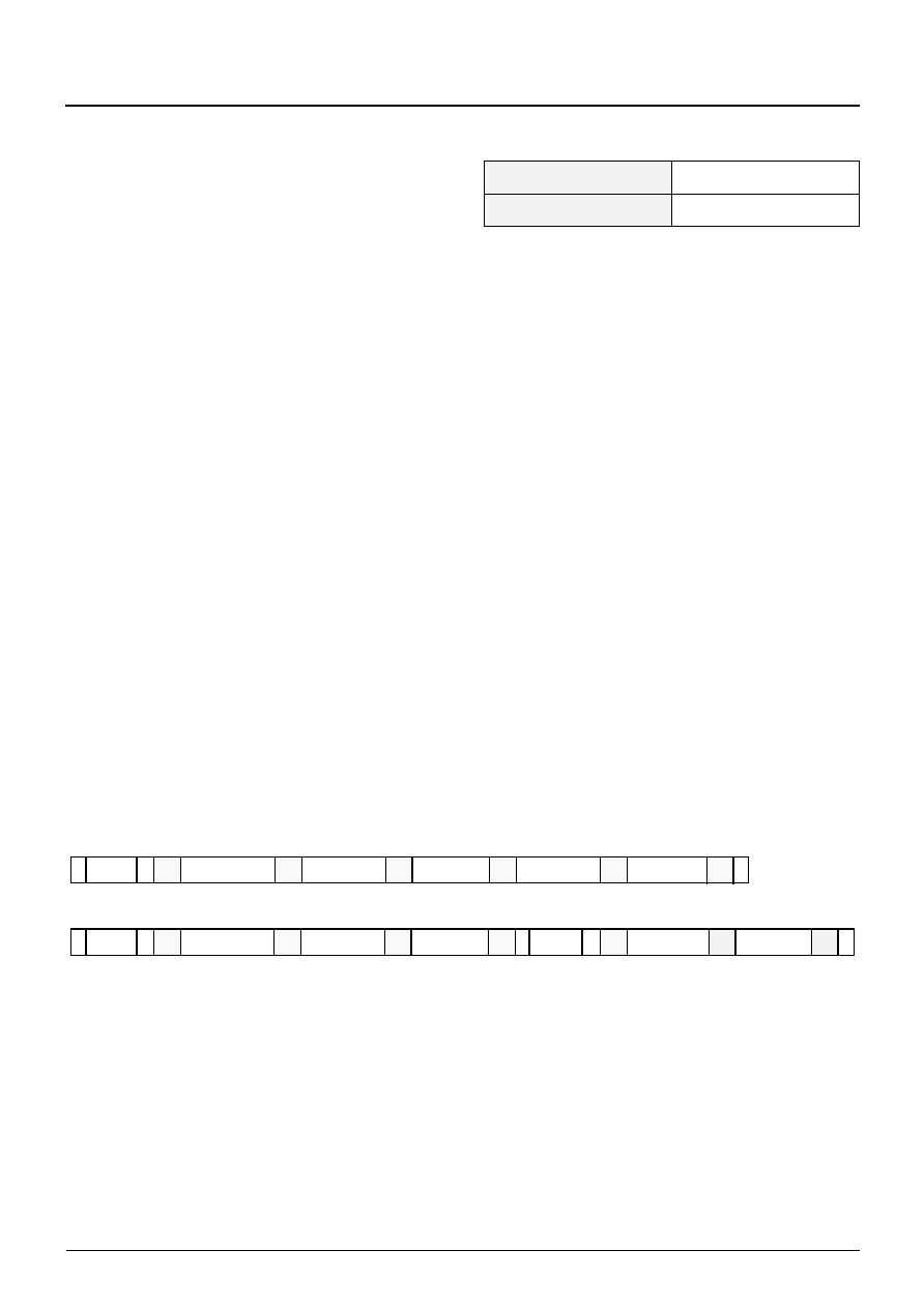
address and reading two bytes of data. Fig. 3–3 shows
I2C protocol for read and write operations.Table 3–5
on page 29 gives definitions of the XDFP control and
status registers. If these registers are smaller than 16
bit the remaining bits should be 0 on write and read
operations. Due to the internal architecture, the IC
cannot react immediately to an I2C requests, which
interacts with the onchip controller. The maximum
response timing is appr. 20 ms. If the addressed con-
troller is not ready for further transmissions on the I2C-
bus, the clock line SCL is pulled low. This puts the cur-
rent transmission into a wait state. After a certain
period of time the clock line will be released and the
interrupted transmission is carried on.
A hardware reset initializes all control registers to 0.
The automatic chip initialization loads a selected set of
registers with the default values given in Table 3–5 on
The register modes are
8/16- bit width
r
read only register
w
write only register
r/w
write/read data register
Note: set unused bits to ‘0‘!
The mnemonics used in the Micronas demo software
are given in the last column.
Fig. 3–3: XDFP protocol
Table 3–3: XDFP read/write address
XDFP Read address
h’13
XDFP Write address
h’12
Ack
Nak
Ack
Start condition
Stop condition
W
R
Ack
Nak
S
P
=
1 (Read bit)
0 (Write bit)
=
0 (Acknowledge bit from DDP = grey
1 (Not acknowledge bit from Controller = hatched or
Write to XDFP control register:
Read from XDFP control register:
S 1000101 W
XDFP-readaddr.
Ack
P
S 1000101 R
highbyte addr.
lowbyte addr.
lowbyte data
Ack highbyte data
or Controller = hatched)
indicating an error state from DDP = grey)
Ack
S 1000101 W
XDFP-writeaddr.
Ack
P
highbyte addr.
lowbyte addr.
lowbyte data
highbyte data
相关PDF资料 |
PDF描述 |
|---|---|
| DDQ24W7P043A00LF | 24 CONTACT(S), MALE, D SUBMINIATURE CONNECTOR, SOLDER |
| DDQ24W7PA00LF | 24 CONTACT(S), MALE, D SUBMINIATURE CONNECTOR, SOLDER |
| DDQ36W4P043A00LF | 36 CONTACT(S), MALE, D SUBMINIATURE CONNECTOR, SOLDER |
| DDQ36W4PA00LF | 36 CONTACT(S), MALE, D SUBMINIATURE CONNECTOR, SOLDER |
| DDQ47W1P043A00LF | 47 CONTACT(S), MALE, D SUBMINIATURE CONNECTOR, SOLDER |
相关代理商/技术参数 |
参数描述 |
|---|---|
| DDP-37CT | 制造商:Pan Pacific 功能描述: |
| DDP400-P1 | 制造商:CCM Assembly & Manufacturing 功能描述:AC Input Cable for ROAL DDP400 series, Bulk |
| DDP400-P4 | 制造商:CCM Assembly & Manufacturing 功能描述:DC Output Cable for ROAL DDP400 series, Bulk |
| DDP400-P6 | 制造商:CCM Assembly & Manufacturing 功能描述:Signal Cable for ROAL DDP400 series, Bulk |
| DDP400-US12-FF | 制造商:ROAL Electronics 功能描述:AC/DC 400W 12V Single Output Enclosed Front Fan, Bulk |
发布紧急采购,3分钟左右您将得到回复。