- 您现在的位置:买卖IC网 > PDF目录171067 > DDP3315CQA (MICRONAS SEMICONDUCTOR HOLDING AG) SPECIALTY CONSUMER CIRCUIT, PQFP80 PDF资料下载
参数资料
| 型号: | DDP3315CQA |
| 厂商: | MICRONAS SEMICONDUCTOR HOLDING AG |
| 元件分类: | 消费家电 |
| 英文描述: | SPECIALTY CONSUMER CIRCUIT, PQFP80 |
| 封装: | PLASTIC, QFP-80 |
| 文件页数: | 8/62页 |
| 文件大小: | 1746K |
| 代理商: | DDP3315CQA |
第1页第2页第3页第4页第5页第6页第7页当前第8页第9页第10页第11页第12页第13页第14页第15页第16页第17页第18页第19页第20页第21页第22页第23页第24页第25页第26页第27页第28页第29页第30页第31页第32页第33页第34页第35页第36页第37页第38页第39页第40页第41页第42页第43页第44页第45页第46页第47页第48页第49页第50页第51页第52页第53页第54页第55页第56页第57页第58页第59页第60页第61页第62页
ADVANCE INFORMATION
16
Micronas
2.2.5. Average Beam Current Limiter
The average beam current limiter (BCL) works on both
the digital YCrCb input and the inserted analog RGB
signals by using either the sense input or the RSW1
input for the beam current measurement. The BCL
uses a different filter to average the beam current dur-
ing the active picture resulting in a 12-bit resolution.
The filter bandwidth is approximately 4 kHz.
The beam current limiter allows the setting of a thresh-
old current, a gain and an additional time constant. If
the beam current is above the threshold, the excess
current is low-pass filtered with the according gain and
time constant. The result is used to attenuate the RGB
outputs by adjusting the white drive multipliers for the
internal (digital) RGB signals, and the analog contrast
multipliers for the analog RGB inputs, respectively.
The lower limit of the attenuator is programmable, thus
a minimum contrast can always be set. If the minimum
contrast is reached, the brightness will be decreased
to a programmable minimum as well. Typical charac-
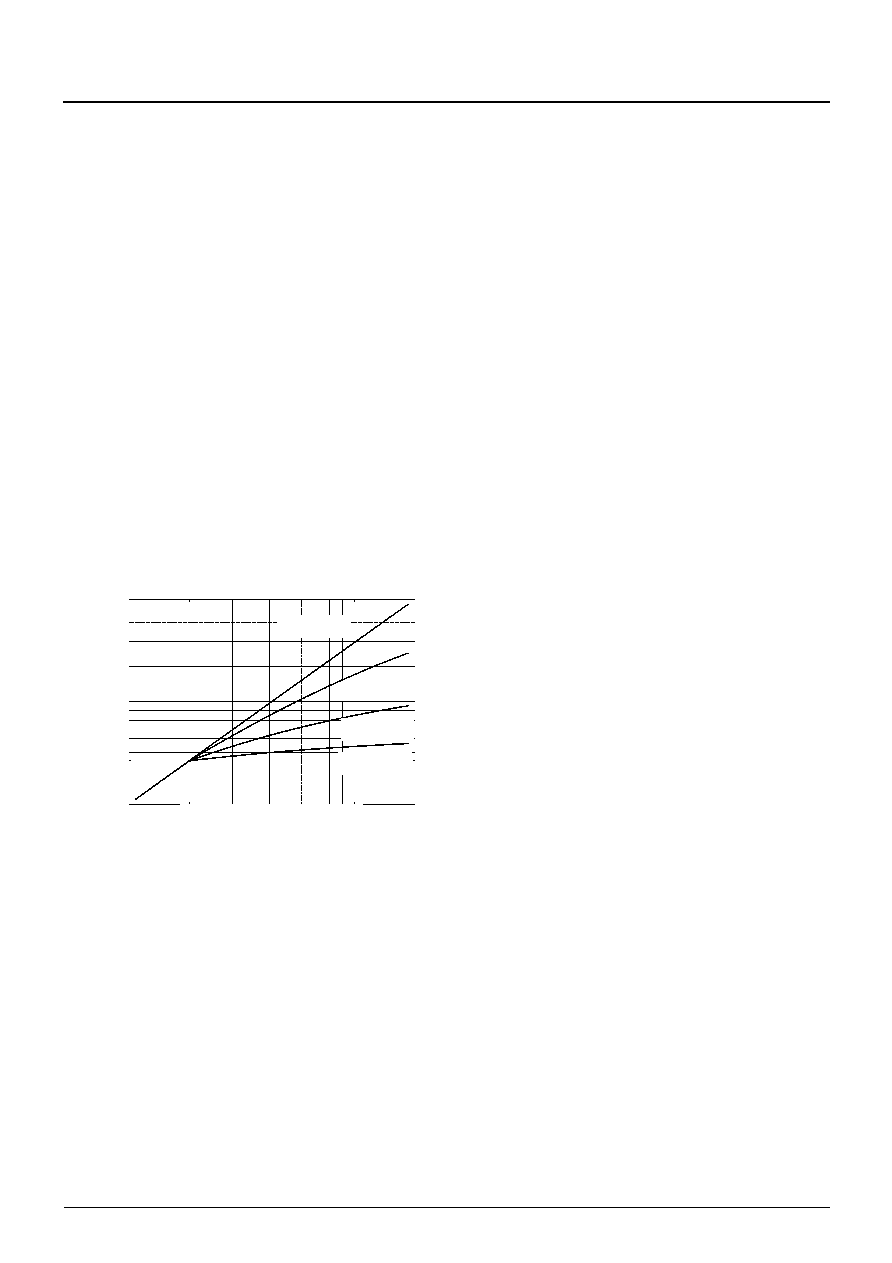
teristics of the BCL for different loop gains are shown
in Fig. 2–14; for this example the tube has been
assumed to have square law characteristics.
Fig. 2–14: Beam current limiter characteristics:
beam current output vs. drive
2.3. Synchronization and Deflection
2.3.1. Deflection Processing
The deflection processing generates the signals for the
horizontal and vertical drive (see Fig. 2–15). This block
contains two numeric phase-locked loops and a secu-
rity unit:
– PLL2 generates the horizontal and vertical timing,
e.g. blanking, clamping and sync signals. Phase
and frequency are synchronized by the incoming
sync signals.
– PLL3 adjusts the phase of the horizontal drive pulse
and compensates for the delay of the horizontal out-
put stage.
– The security unit observes the H-Drive output sig-
nal. With an external 5 MHz reference clock this unit
controls the H-drive “off time” and period. In case of
an incorrect H-drive signal the security unit gener-
ates a free running h-drive signal divided down from
the 5 MHz reference clock.
The DDP 3315C is able to synchronize to various hori-
zontal frequencies, even VGA frequencies. Supported
horizontal input frequencies are listed in Table 2–6.
2.3.2. Security Unit for H-Drive
The security unit observes the H-Drive output signal
with an external 5 MHz reference clock. For different
horizontal frequencies the security unit uses different
ranges to control the H-Drive signal. Selecting a spe-
cific horizontal frequency via I2C-Register HFREQ,
automatically switches to the corresponding security
range. The control ranges are listed in Table 2–6.
The window of the control range has to lie within a
main control window which is selectable with the
FREQSEL input pin. With a low signal at this pin the
main control range is 28.8... 34.4
s and with a high
signal the main control range is 25.6... 29.2
s.
This is to prevent male functions if the horizontal
deflection stage is prepared for VGA frequencies.
The Horizontal Drive Output can be forced to the high
level during Flyback. This means, the falling edge of
the drive pulse is earliest possible at the end of the fly-
back pulse. This function can be enabled via the I2C
bus (EFLB).
be
am
c
u
rr
ent
drive
gain = 0%
gain = 10%
gain = 60%
gain = 90%
threshold
11.5
2
1
1.5
2
3
5
相关PDF资料 |
PDF描述 |
|---|---|
| DDQ24W7P043A00LF | 24 CONTACT(S), MALE, D SUBMINIATURE CONNECTOR, SOLDER |
| DDQ24W7PA00LF | 24 CONTACT(S), MALE, D SUBMINIATURE CONNECTOR, SOLDER |
| DDQ36W4P043A00LF | 36 CONTACT(S), MALE, D SUBMINIATURE CONNECTOR, SOLDER |
| DDQ36W4PA00LF | 36 CONTACT(S), MALE, D SUBMINIATURE CONNECTOR, SOLDER |
| DDQ47W1P043A00LF | 47 CONTACT(S), MALE, D SUBMINIATURE CONNECTOR, SOLDER |
相关代理商/技术参数 |
参数描述 |
|---|---|
| DDP-37CT | 制造商:Pan Pacific 功能描述: |
| DDP400-P1 | 制造商:CCM Assembly & Manufacturing 功能描述:AC Input Cable for ROAL DDP400 series, Bulk |
| DDP400-P4 | 制造商:CCM Assembly & Manufacturing 功能描述:DC Output Cable for ROAL DDP400 series, Bulk |
| DDP400-P6 | 制造商:CCM Assembly & Manufacturing 功能描述:Signal Cable for ROAL DDP400 series, Bulk |
| DDP400-US12-FF | 制造商:ROAL Electronics 功能描述:AC/DC 400W 12V Single Output Enclosed Front Fan, Bulk |
发布紧急采购,3分钟左右您将得到回复。