- 您现在的位置:买卖IC网 > PDF目录171067 > DDP3315CQA (MICRONAS SEMICONDUCTOR HOLDING AG) SPECIALTY CONSUMER CIRCUIT, PQFP80 PDF资料下载
参数资料
| 型号: | DDP3315CQA |
| 厂商: | MICRONAS SEMICONDUCTOR HOLDING AG |
| 元件分类: | 消费家电 |
| 英文描述: | SPECIALTY CONSUMER CIRCUIT, PQFP80 |
| 封装: | PLASTIC, QFP-80 |
| 文件页数: | 6/62页 |
| 文件大小: | 1746K |
| 代理商: | DDP3315CQA |
第1页第2页第3页第4页第5页当前第6页第7页第8页第9页第10页第11页第12页第13页第14页第15页第16页第17页第18页第19页第20页第21页第22页第23页第24页第25页第26页第27页第28页第29页第30页第31页第32页第33页第34页第35页第36页第37页第38页第39页第40页第41页第42页第43页第44页第45页第46页第47页第48页第49页第50页第51页第52页第53页第54页第55页第56页第57页第58页第59页第60页第61页第62页
ADVANCE INFORMATION
14
Micronas
2.2.2. Fast Blank Monitor
The presence of external analog RGB sources can be
detected by means of a fast blank monitor. The status
of the selected fast blank input can be monitored via
an I2C register. There is a 2 bit information, giving
static and dynamic indication of a fast blank signal.
The static bit is directly reading the fast blank input
line, whereas the dynamic bit is reading the status of a
flip flop triggered by the negative edge of the fast blank
signal.
With this monitor logic it is possible to detect if there is
an external RGB source active and if it is a full screen
insertion or only a box. The monitor logic is connected
directly to the FBLIN1 or FBLIN2 pin. Selection is done
via I2C register.
2.2.3. Half Contrast Control
Insertion of transparent text pages or OSD onto the
video picture is often difficult to read, especially if the
video contrast is high. The DDP 3315C features a con-
trast reduction of the video background of 30 or 50%
by means of a half contrast input (HCS pin). This input
can be supplied with a fast switching signal (similar to
the fast blank input), typically defining a rectangular
box. Inside this box the video picture is displayed with
reduced contrast, while the analog component signals
are still displayed with full contrast.
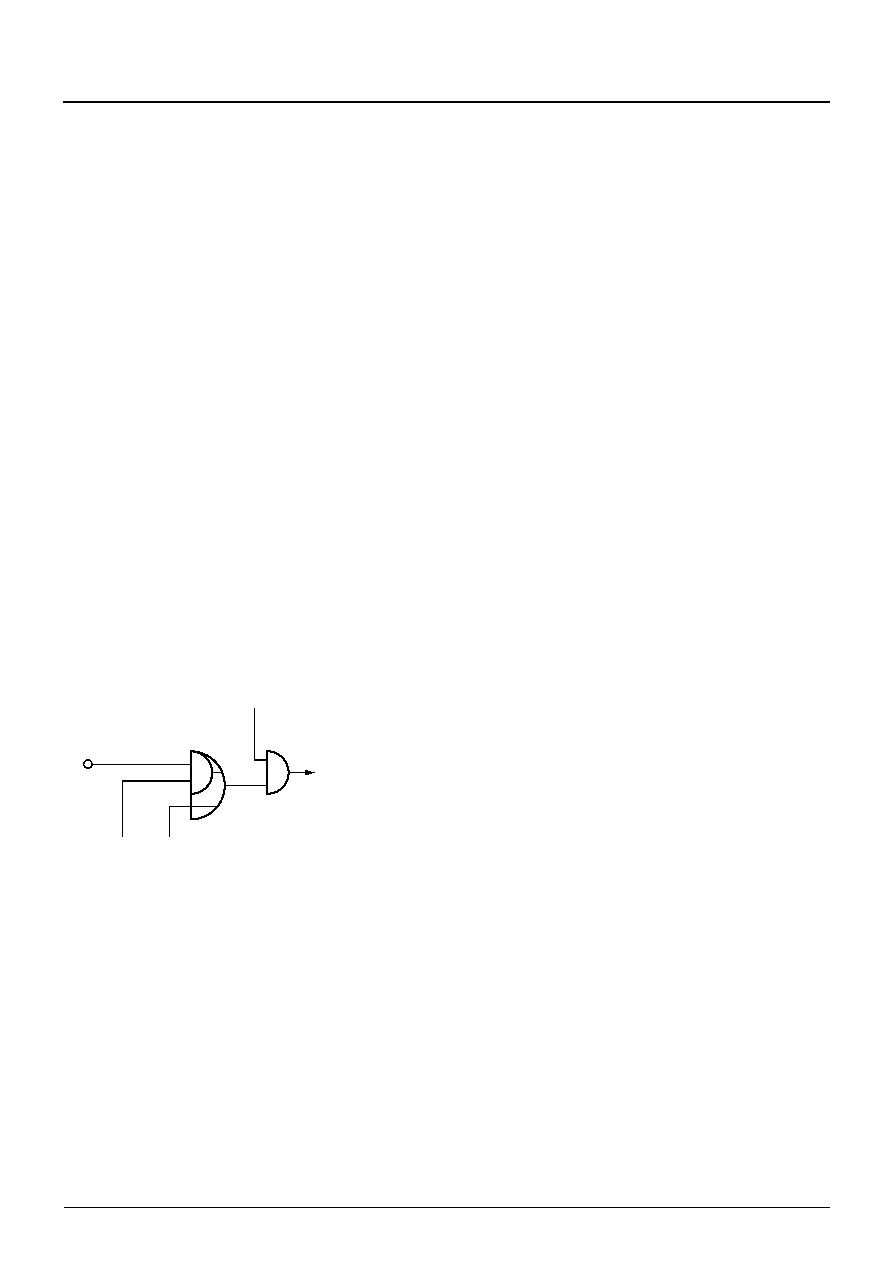
Fig. 2–11: Half Contrast switch logic
2.2.4. CRT Measurement and Control
In order to define accurate color on different CRT dis-
plays, the cut-off and white drive settings have to be
adjusted depending on the characteristic of CRT phos-
phor. To guarantee correct colors during the for the
lifetime of the display, a build in automatic tube control
loop measures and adjusts the black level on every
field and white point every third field.
The display processor is equipped with an 9/12-bit
PDM-ADC for all picture tube measuring purposes.
This MADC is connected to the SENSE input pin, the
input range is 0 to 2.6 V.
Cutoff and white drive current measurement are car-
ried out with 8-bit resolution during the vertical blank-
ing interval. The current range for cutoff measurement
is set by connecting the sense resistor R1 to the
SENSE input. Due to the fact of a 1:10 relation
between cutoff and white drive current the range select
2 output (RSW2) becomes active for the white drive
measurement and connects R3 in parallel to R1, thus
determining the correct current range. During the
active picture, the MADC is used for the average beam
current limiter with a 12-bit resolution. Again a different
measurement range is selected with active range
select 1&2 outputs (RSW1&RSW2) connecting R2 in
the corresponding timing.
These measurements are typically done at the sum-
mation point of the picture tube cathode currents.
Another method uses two different current measure-
ments:
– The range switch 1 pin (RSW1) can be used as a
second sense input, selectable by software. In this
case, the cutoff and white drive currents are mea-
sured as before at the SENSE input.
– The active picture measurement can be done with
the second sense input (RSW1). The signal may
come (via a proper interface) from the low end of the
EHT coil (CRT anode current). In this case, the
resistor R2 in Fig. 2–12 has to be removed.
The picture tube measurement returns results on
every field for:
– cutoff R
– cutoff G
– cutoff B
– white drive R or G or B (sequentially)
HCS
HCSPOL
HCS intern
HCSEN
HCSFOH
#
相关PDF资料 |
PDF描述 |
|---|---|
| DDQ24W7P043A00LF | 24 CONTACT(S), MALE, D SUBMINIATURE CONNECTOR, SOLDER |
| DDQ24W7PA00LF | 24 CONTACT(S), MALE, D SUBMINIATURE CONNECTOR, SOLDER |
| DDQ36W4P043A00LF | 36 CONTACT(S), MALE, D SUBMINIATURE CONNECTOR, SOLDER |
| DDQ36W4PA00LF | 36 CONTACT(S), MALE, D SUBMINIATURE CONNECTOR, SOLDER |
| DDQ47W1P043A00LF | 47 CONTACT(S), MALE, D SUBMINIATURE CONNECTOR, SOLDER |
相关代理商/技术参数 |
参数描述 |
|---|---|
| DDP-37CT | 制造商:Pan Pacific 功能描述: |
| DDP400-P1 | 制造商:CCM Assembly & Manufacturing 功能描述:AC Input Cable for ROAL DDP400 series, Bulk |
| DDP400-P4 | 制造商:CCM Assembly & Manufacturing 功能描述:DC Output Cable for ROAL DDP400 series, Bulk |
| DDP400-P6 | 制造商:CCM Assembly & Manufacturing 功能描述:Signal Cable for ROAL DDP400 series, Bulk |
| DDP400-US12-FF | 制造商:ROAL Electronics 功能描述:AC/DC 400W 12V Single Output Enclosed Front Fan, Bulk |
发布紧急采购,3分钟左右您将得到回复。