- 您现在的位置:买卖IC网 > PDF目录67672 > GT-48004A (Galileo Technology Services, LLC) Four Port Switched Fast Ethernet Controller(四端口、交换式快速以太网控制器) PDF资料下载
参数资料
| 型号: | GT-48004A |
| 厂商: | Galileo Technology Services, LLC |
| 英文描述: | Four Port Switched Fast Ethernet Controller(四端口、交换式快速以太网控制器) |
| 中文描述: | 四端口交换式快速以太网控制器(四端口,交换式快速以太网控制器) |
| 文件页数: | 78/106页 |
| 文件大小: | 953K |
| 代理商: | GT-48004A |
第1页第2页第3页第4页第5页第6页第7页第8页第9页第10页第11页第12页第13页第14页第15页第16页第17页第18页第19页第20页第21页第22页第23页第24页第25页第26页第27页第28页第29页第30页第31页第32页第33页第34页第35页第36页第37页第38页第39页第40页第41页第42页第43页第44页第45页第46页第47页第48页第49页第50页第51页第52页第53页第54页第55页第56页第57页第58页第59页第60页第61页第62页第63页第64页第65页第66页第67页第68页第69页第70页第71页第72页第73页第74页第75页第76页第77页当前第78页第79页第80页第81页第82页第83页第84页第85页第86页第87页第88页第89页第90页第91页第92页第93页第94页第95页第96页第97页第98页第99页第100页第101页第102页第103页第104页第105页第106页
GT-48004A Four Port Switched Fast Ethernet Controller
73
Revision 1.0
N:\Marketing\Docs\Archive\48004A\DATASHEET\Rev 1.0\484ads10.fm
19.
Interrupts
The GT-48004A signals interrupts to a management CPU via the PCI INTA# pin. Interrupts are maskable through the
Interrupt Mask register and the interrupt source is determined through the Interrupt Cause register. The Interrupt Mask
register defaults to masking all interrupts. A ‘0’ in the appropriate bit means that particular interrupt will be masked. A ‘1’
in the appropriate bit means that particular interrupt will not be masked. The default is that all interrupts are masked.
Interrupts are cleared by writing ‘0’ to the corresponding bit in the Interrupt Cause register. Writing ‘1’ to a bit in the
Cause register has no effect.
NOTE: There is an Interrupt Cause and Mask register in each FEU. The interrupts requested by each FEU are ORed
before being brought out to the package pin.
20.
RESET Configuration
The GT-48004A uses several pins as configuration inputs to set certain parameters following a RESET. The definition
of the configuration pins changes immediately after RESET to their usual function.
20.1
Configuration Pins
Configuration pins must be pulled up or down externally at RESET to select the desired operational parameter. The
recommended value of the pull-up/down resistors is 4.7K ohms. Table 34 shows the configuration pins for the GT-
48004A.
20.2
Configuration Input Timings
The configuration inputs have two timing requirements:
setup/hold time to clock (as any synchronous input)
setup of at least 10 clock cycles before RESET de-assertion (rising edge).
You can guarantee these parameters by using resistors to strap the configuration pins and delaying RESET de-asser-
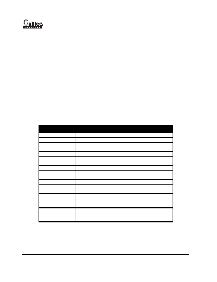
Table 34: RESET Pin Strapping Options
Pin
Co nf igur at ion Fu nct i on
A/BDAddr[4:0]
Device Number: Each FEU must have a different device number.
A/BDAddr[5]
DRAM Size for FEU
0-
1-
2Mbyte
1Mbyte
A/BDAddr[6]
Half/Full Duplex Mode for Port 0/2
0-
1-
Half Duplex
Full Duplex
A/BDAddr[7]
Half/Full Duplex Mode for Port 1/3
0-
1-
Half Duplex
Full Duplex
A/BDAddr[8]
DRAM Type for each FEU
0-
1-
Reserved
EDO
LEDMode*
LED Mode
0-
1-
LEDMode 0
LEDMode 1
ForceLinkPass*
Force Link Pass
0-
1-
Read Link Status from the PHY via SMI
Force Link Status to “link is up”
相关PDF资料 |
PDF描述 |
|---|---|
| GT-48006A | Low Cost Two Port 10/100Mbps Ethernet Bridge/Switch Controller(低成本、双端口10/100Mbps以太网桥式/交换式控制器) |
| GT-48207 | Advanced Switched Ethernet Controllers for 10+10/100 BaseX(高级交换式 10+10/100 BaseX以太网控制器) |
| GT-48208 | Advanced Switched Ethernet Controllers for 10+10/100 BaseX(高级交换式 10+10/100 BaseX以太网控制器) |
| GT-48212 | Advanced Switched Ethernet Controllers for 10+10/100 BaseX(高级交换式 10+10/100 BaseX以太网控制器) |
| GT-64010A | System Controller with PCI Interface for R4XXX/ R5000 Family CPUs(带PCI接口用于R4XXX/ R5000 系列 CPUs的系统控制器) |
相关代理商/技术参数 |
参数描述 |
|---|---|
| GT482 | 制造商:CORNELL DUBILIER ELECTRONICS 功能描述:Cap Ceramic 82pF 3000V SL 5% (12 X 6mm) Radial 9.5mm 85°C |
| GT48212-A6-PBB1C000 | 制造商:Marvell 功能描述: |
| GT48212-A6-PBB-C000 | 制造商:Marvell 功能描述:12 PORT E + 2 PORT FE SWITCH (MANAGED) - Trays |
| GT48300-A1-BBE1C083 | 制造商:Marvell 功能描述:Marvell GT48300-A1-BBE1C083 |
| GT48300-A1-BBE-C000 | 制造商:Marvell 功能描述:Marvell GT48300-A1-BBE-C000 |
发布紧急采购,3分钟左右您将得到回复。