- 您现在的位置:买卖IC网 > PDF目录20679 > ISL6329CRZ (Intersil)IC CTRLR PWM SYNC BUCK DL 60QFN PDF资料下载
参数资料
| 型号: | ISL6329CRZ |
| 厂商: | Intersil |
| 文件页数: | 12/38页 |
| 文件大小: | 0K |
| 描述: | IC CTRLR PWM SYNC BUCK DL 60QFN |
| 标准包装: | 43 |
| 应用: | 控制器,AMD SVI |
| 输入电压: | 5 V ~ 12 V |
| 输出数: | 2 |
| 输出电压: | 0.0125 V ~ 1.55 V |
| 工作温度: | 0°C ~ 70°C |
| 安装类型: | * |
| 封装/外壳: | * |
| 供应商设备封装: | * |
| 包装: | * |
第1页第2页第3页第4页第5页第6页第7页第8页第9页第10页第11页当前第12页第13页第14页第15页第16页第17页第18页第19页第20页第21页第22页第23页第24页第25页第26页第27页第28页第29页第30页第31页第32页第33页第34页第35页第36页第37页第38页
�� �
�
�ISL6329�
�Timing� Diagram�
�t� PDHUGATE�
�UGATE�
�LGATE�
�t� FLGATE�
�t� RUGATE�
�t� FUGATE�
�t� RLGATE�
�t� PDHLGATE�
�Operation�
�The� ISL6329� utilizes� a� multiphase� architecture� to� provide� a� low�
�cost,� space� saving� power� conversion� solution� for� the� processor�
�core� voltage.� The� controller� also� implements� a� simple� single�
�phase� architecture� to� provide� the� Northbridge� voltage� on� the�
�same� chip.�
�NOTE:� All� references� to� VCC� refer� to� the� VCC� pin� or� the� node� that�
�is� tied� to� the� VCC� pin.� This� should� not� be� confused� with� the� bias�
�voltage� as� the� bias� rail� can� be� separated� from� the� VCC� node� by�
�an� RC� filter� resistor.�
�Multiphase� Power� Conversion�
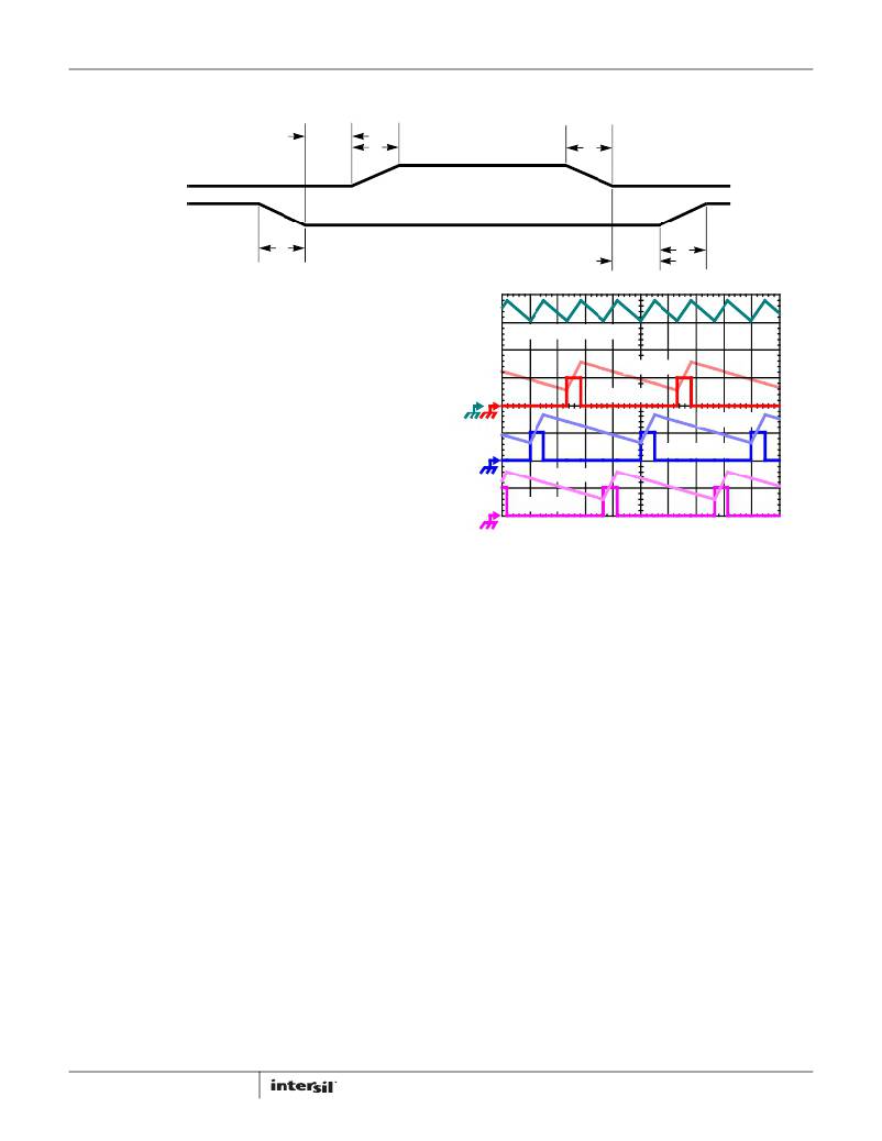
�IL1� +� IL2� +� IL3,� 7A/DIV�
�IL3, 7A/DIV�
�PWM3, 5V/DIV�
�IL2, 7A/DIV�
�PWM2, 5V/DIV�
�IL1, 7A/DIV�
�Microprocessor� load� current� profiles� have� changed� to� the� point�
�that� the� advantages� of� multiphase� power� conversion� are�
�PWM1, 5V/DIV�
�1μs/DIV�
�impossible� to� ignore.� The� technical� challenges� associated� with�
�producing� a� single-phase� converter� that� is� both� cost-effective� and�
�thermally� viable� have� forced� a� change� to� the� cost-saving�
�approach� of� multiphase.� The� ISL6329� controller� helps� simplify�
�implementation� by� integrating� vital� functions� and� requiring�
�FIGURE� 1.� PWM� AND� INDUCTOR-CURRENT� WAVEFORMS� FOR�
�3-PHASE� CONVERTER�
�To� understand� the� reduction� of� ripple� current� amplitude� in� the�
�multiphase� circuit,� examine� Equation� 2,� which� represents� an�
�individual� channel� peak-to-peak� inductor� current.�
�(� V� IN� –� V� OUT� )� V� OUT�
���conversion� using� the� ISL6329� controller.�
�I� PP� =� ------------------------------------------------------�
�L� f� S� V� IN�
�(EQ.� 2)�
�I� C� ,� PP� =� ------------------------------------------------------------�
�Interleaving�
�The� switching� of� each� channel� in� a� multiphase� converter� is� timed�
�to� be� symmetrically� out-of-phase� with� each� of� the� other� channels.�
�In� a� 3-phase� converter,� each� channel� switches� 1/3� cycle� after� the�
�previous� channel� and� 1/3� cycle� before� the� following� channel.� As�
�a� result,� the� 3-phase� converter� has� a� combined� ripple� frequency�
�three� times� greater� than� the� ripple� frequency� of� any� one� phase.�
�In� addition,� the� peak-to-peak� amplitude� of� the� combined� inductor�
�currents� is� reduced� in� proportion� to� the� number� of� phases�
�(Equations� 2� and� 3).� Increased� ripple� frequency� and� lower� ripple�
�amplitude� mean� that� the� designer� can� use� less� per-channel�
�inductance� and� lower� total� output� capacitance� for� any�
�performance� specification.�
�Figure� 1� illustrates� the� multiplicative� effect� on� output� ripple�
�frequency.� The� three� channel� currents� (IL1,� IL2,� and� IL3)� combine� to�
�form� the� AC� ripple� current� and� the� DC� load� current.� The� ripple�
�component� has� three� times� the� ripple� frequency� of� each� individual�
�channel� current.� Each� PWM� pulse� is� terminated� 1/3� of� a� cycle� after�
�the� PWM� pulse� of� the� previous� phase.� The� peak-to-peak� current� for�
�each� phase� is� about� 7A,� and� the� DC� components� of� the� inductor�
�currents� combine� to� feed� the� load.�
�12�
�In� Equation� 2,� V� IN� and� V� OUT� are� the� input� and� output� voltages�
�respectively,� L� is� the� single-channel� inductor� value,� and� f� S� is� the�
�switching� frequency.�
�The� output� capacitors� conduct� the� ripple� component� of� the�
�inductor� current.� In� the� case� of� multiphase� converters,� the�
�capacitor� current� is� the� sum� of� the� ripple� currents� from� each� of�
�the� individual� channels.� Compare� Equation� 2� to� the� expression�
�for� the� peak-to-peak� current� after� the� summation� of� N�
�symmetrically� phase-shifted� inductor� currents� in� Equation� 3.�
�Peak-to-peak� ripple� current� decreases� by� an� amount� proportional�
�to� the� number� of� channels.� Output-voltage� ripple� is� a� function� of�
�capacitance,� capacitor� equivalent� series� resistance� (ESR),� and�
�inductor� ripple� current.� Reducing� the� inductor� ripple� current�
�allows� the� designer� to� use� fewer� or� less� costly� output� capacitors.�
�(� V� IN� –� N� V� OUT� )� V� OUT� (EQ.� 3)�
�L� f� S� V� IN�
�Another� benefit� of� interleaving� is� to� reduce� input� ripple� current.�
�Input� capacitance� is� determined� in� part� by� the� maximum� input�
�ripple� current.� Multiphase� topologies� can� improve� overall� system�
�cost� and� size� by� lowering� input� ripple� current� and� allowing� the�
�designer� to� reduce� the� cost� of� input� capacitance.� The� example� in�
�FN7800.0�
�April� 19,� 2011�
�相关PDF资料 |
PDF描述 |
|---|---|
| RSO-123.3DZ/H2 | CONV DC/DC 1W 4.5-18V +/-3.3VOUT |
| ISL6534CVZ-T | IC REG 3OUT BCK/LINEAR 24EPTSSOP |
| ASM31DRMI | CONN EDGECARD 62POS .156 SQ WW |
| GEM28DRKN | CONN EDGECARD 56POS DIP .156 SLD |
| EL7513IYZ-T13 | IC LED DRIVR WHITE BCKLGT 8-MSOP |
相关代理商/技术参数 |
参数描述 |
|---|---|
| ISL6329CRZ-T | 功能描述:电压模式 PWM 控制器 6+1 PHS DL PWM CONTRLR FOR CORE RoHS:否 制造商:Texas Instruments 输出端数量:1 拓扑结构:Buck 输出电压:34 V 输出电流: 开关频率: 工作电源电压:4.5 V to 5.5 V 电源电流:600 uA 最大工作温度:+ 125 C 最小工作温度:- 40 C 封装 / 箱体:WSON-8 封装:Reel |
| ISL6329EVAL1Z | 制造商:Intersil Corporation 功能描述:ISL6329 EVALUATION BOARD - 60 LEAD - QFN - ROHS COMPLIANT - Bulk |
| ISL6329IRZ | 功能描述:电压模式 PWM 控制器 6+1 PHS DL PWM CONTRLR FOR CORE RoHS:否 制造商:Texas Instruments 输出端数量:1 拓扑结构:Buck 输出电压:34 V 输出电流: 开关频率: 工作电源电压:4.5 V to 5.5 V 电源电流:600 uA 最大工作温度:+ 125 C 最小工作温度:- 40 C 封装 / 箱体:WSON-8 封装:Reel |
| ISL6329IRZ-T | 功能描述:电压模式 PWM 控制器 6+1 PHS DL PWM CONTRLR FOR CORE RoHS:否 制造商:Texas Instruments 输出端数量:1 拓扑结构:Buck 输出电压:34 V 输出电流: 开关频率: 工作电源电压:4.5 V to 5.5 V 电源电流:600 uA 最大工作温度:+ 125 C 最小工作温度:- 40 C 封装 / 箱体:WSON-8 封装:Reel |
| ISL6333ACRZ | 功能描述:IC CTRLR PWM 3PHASE BUCK 48-QFN RoHS:是 类别:集成电路 (IC) >> PMIC - 稳压器 - 专用型 系列:- 标准包装:43 系列:- 应用:控制器,Intel VR11 输入电压:5 V ~ 12 V 输出数:1 输出电压:0.5 V ~ 1.6 V 工作温度:-40°C ~ 85°C 安装类型:表面贴装 封装/外壳:48-VFQFN 裸露焊盘 供应商设备封装:48-QFN(7x7) 包装:管件 |
发布紧急采购,3分钟左右您将得到回复。