- 您现在的位置:买卖IC网 > PDF目录5055 > MAX17080GTL+ (Maxim Integrated Products)IC CONTROLLER AMD SVI 40-TQFN PDF资料下载
参数资料
| 型号: | MAX17080GTL+ |
| 厂商: | Maxim Integrated Products |
| 文件页数: | 42/48页 |
| 文件大小: | 0K |
| 描述: | IC CONTROLLER AMD SVI 40-TQFN |
| 标准包装: | 60 |
| 应用: | 控制器,AMD SVI |
| 输入电压: | 2.7 V ~ 5.5 V |
| 输出数: | 3 |
| 输出电压: | 0.013 V ~ 1.55 V |
| 工作温度: | -40°C ~ 105°C |
| 安装类型: | 表面贴装 |
| 封装/外壳: | 40-WFQFN 裸露焊盘 |
| 供应商设备封装: | 40-TQFN-EP(5x5) |
| 包装: | 管件 |
第1页第2页第3页第4页第5页第6页第7页第8页第9页第10页第11页第12页第13页第14页第15页第16页第17页第18页第19页第20页第21页第22页第23页第24页第25页第26页第27页第28页第29页第30页第31页第32页第33页第34页第35页第36页第37页第38页第39页第40页第41页当前第42页第43页第44页第45页第46页第47页第48页
�� �
�
�AMD� 2-/3-Output� Mobile� Serial�
�VID� Controller�
�When� using� low-capacity� ceramic� filter� capacitors,�
�capacitor� size� is� usually� determined� by� the� capacity�
�needed� to� prevent� V� SOAR� from� causing� problems� during�
�load� transients.� Generally,� once� enough� capacitance� is�
�added� to� meet� the� overshoot� requirement,� undershoot� at�
�the� rising� load� edge� is� no� longer� a� problem.�
�NB� Transient� Droop� and� Stability�
�The� voltage-positioned� load-line� of� the� NB� SMPS� also�
�provides� the� AC� ripple� voltage� required� for� stability.� To�
�maintain� stability,� the� output� capacitive� ripple� must� be�
�kept� smaller� than� the� internal� AC� ripple� voltage.� Hence,�
�a� minimum� NB� output� capacitance� is� required� as� calcu-�
�?� ?� 1� +� V�
�NB Input Capacitor Selection�
�The� input� capacitor� must� meet� the� ripple-current� require-�
�ment� (I� RMS� )� imposed� by� the� switching� currents.� The� I� RMS�
�lated� below:�
�:� C� OUT� 3� >�
�2� � f� SW� 3�
�1�
�� R� DROOP� 3� (� MIN� )�
�?� V� OUT� 3� ?�
�?�
�IN� 3� ?�
�I� RMS� =� ?� LOAD� 3� ?� V� OUT� 3� (� V� IN� 3� ?� V� OUT� 3� )�
�?� I� ?�
�R� PULLUP� ≤�
�requirements can be determined by the following equation:�
�:�
�?� V� IN� 3� ?�
�The� worst-case� RMS� current� requirement� occurs� when�
�operating� with� V� IN3� =� 2V� OUT3� .� At� this� point,� the� above�
�equation� simplifies� to� I� RMS� =� 0.5� x� I� LOAD3� .�
�For� most� applications,� nontantalum� chemistries�
�(ceramic,� aluminum,� or� OS-CON)� are� preferred� due� to�
�their� resistance� to� inrush� surge� currents� typical� of� sys-�
�tems� with� a� mechanical� switch� or� connector� in� series�
�with� the� input.� The� MAX17080� NB� regulator� is� operated�
�as� the� second� stage� of� a� two-stage� power-conversion�
�system.� Tantalum� input� capacitors� are� acceptable.�
�Choose� an� input� capacitor� that� exhibits� less� than� 10� °� C�
�temperature� rise� at� the� RMS� input� current� for� optimal�
�circuit� longevity.�
�NB� Steady-State� Voltage� Positioning�
�Voltage� positioning� dynamically� lowers� the� output� volt-�
�age� in� response� to� the� load� current,� reducing� the� out-�
�put� capacitance� and� processor� ’s� power-dissipation�
�requirements.� For� NB,� the� load� line� is� generated� by�
�sensing� the� inductor� current� through� the� high-side�
�MOSFET� on-resistance� (R� ON(NH3)� ),� and� is� internally�
�preset� to� -6.5mV/A� (typ).� This� guarantees� the� output�
�voltage� to� stay� in� the� static� regulation� window� over� the�
�maximum� load� conditions� per� AMD� specifications.� See�
�Table� 7� for� full-load� voltage� droop� according� to� differ-�
�ent� ILIM3� settings.�
�SVD�
�SVC�
�S�
�where� R� DROOP3(MIN)� is� 4.5mV/A� as� defined� in� the�
�Electrical� Characteristics� table,� and� f� SW3� is� the� NB�
�switching� frequency� programmed� by� the� OSC� pin.�
�SVI� Applications� Information�
�I� 2� C� Bus-Compatible� Interface�
�The� MAX17080� is� a� receive-only� device.� The� 2-wire� seri-�
�al� bus� (pins� SVC� and� SVD)� is� designed� to� attach� on� a�
�low-voltage� I� 2� C-like� bus.� In� the� AMD� mobile� application,�
�the� CPU� directly� drives� the� bus� at� a� speed� of� 3.4MHz.�
�The� CPU� has� a� push-pull� output� driving� to� the� V� DDIO�
�voltage� level.� External� pullup� resistors� are� not� required.�
�When� not� used� in� the� specific� AMD� application,� the� ser-�
�ial� interface� can� be� driven� to� as� high� as� 2.5V,� and� can�
�operate� at� the� lower� speeds� (100kHz,� 400kHz,� or�
�1.7MHz).� At� lower� clock� speeds,� external� pullup� resis-�
�tors� can� be� used� for� open-drain� outputs.� Connect� both�
�SVC� and� SVD� lines� to� V� DDIO� through� individual� pullup�
�resistors.� Calculate� the� required� value� of� the� pullup�
�resistors� using:�
�:� t� R�
�C� BUS�
�where� t� R� is� the� rise� time,� and� should� be� less� than� 10%� of�
�the� clock� period.� C� BUS� is� the� total� capacitance� on� the� bus.�
�The� MAX17080� is� compatible� with� the� standard� SVI� inter-�
�face� protocol� as� defined� in� the� following� subsections.�
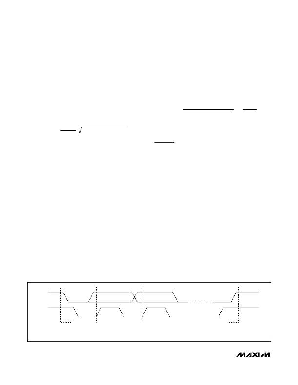
�Figure� 11� shows� the� SVI� bus� START,� STOP,� and� data�
�change� conditions.�
�P�
�START�
�CONDITION�
�DATA� LINE�
�STABLE�
�DATA� VALID�
�CHANGE�
�OF� DATA�
�ALLOWED�
�STOP�
�CONDITION�
�Figure� 11.� SVI� Bus� START,� STOP,� and� Data� Change� Conditions�
�42�
�______________________________________________________________________________________�
�相关PDF资料 |
PDF描述 |
|---|---|
| GBA49DRMS | CONN EDGECARD 98POS .125 SQ WW |
| X5649S14I-2.7A | IC SUPERVISOR CPU 64K EE 14-SOIC |
| X5649S14I-2.7 | IC SUPERVISOR CPU 64K EE 14-SOIC |
| P1330R-333K | INDUCTOR POWER 33.0UH SMD |
| P1330-333K | INDUCTOR POWER 33.0UH SMD |
相关代理商/技术参数 |
参数描述 |
|---|---|
| MAX17080GTL+ | 功能描述:开关变换器、稳压器与控制器 Integrated Circuits (ICs) Voltage Regulators - Special Purpose - IC CONTROLLER AMD SVI 40-TQFN RoHS:否 制造商:Texas Instruments 输出电压:1.2 V to 10 V 输出电流:300 mA 输出功率: 输入电压:3 V to 17 V 开关频率:1 MHz 工作温度范围: 安装风格:SMD/SMT 封装 / 箱体:WSON-8 封装:Reel |
| MAX17080GTL+T | 功能描述:开关变换器、稳压器与控制器 Integrated Circuits (ICs) Voltage Regulators - Special Purpose - IC CONTROLLER AMD SVI 40-TQFN RoHS:否 制造商:Texas Instruments 输出电压:1.2 V to 10 V 输出电流:300 mA 输出功率: 输入电压:3 V to 17 V 开关频率:1 MHz 工作温度范围: 安装风格:SMD/SMT 封装 / 箱体:WSON-8 封装:Reel |
| MAX17081EVKIT+ | 功能描述:电源管理IC开发工具 RoHS:否 制造商:Maxim Integrated 产品:Evaluation Kits 类型:Battery Management 工具用于评估:MAX17710GB 输入电压: 输出电压:1.8 V |
| MAX17081EWV+ | 功能描述:电池管理 RoHS:否 制造商:Texas Instruments 电池类型:Li-Ion 输出电压:5 V 输出电流:4.5 A 工作电源电压:3.9 V to 17 V 最大工作温度:+ 85 C 最小工作温度:- 40 C 封装 / 箱体:VQFN-24 封装:Reel |
| MAX17081EWV+T | 功能描述:电池管理 RoHS:否 制造商:Texas Instruments 电池类型:Li-Ion 输出电压:5 V 输出电流:4.5 A 工作电源电压:3.9 V to 17 V 最大工作温度:+ 85 C 最小工作温度:- 40 C 封装 / 箱体:VQFN-24 封装:Reel |
发布紧急采购,3分钟左右您将得到回复。