- 您现在的位置:买卖IC网 > PDF目录13110 > MAX8550AETI+ (Maxim Integrated Products)IC PWR SUP DDR INTEG 28TQFN PDF资料下载
参数资料
| 型号: | MAX8550AETI+ |
| 厂商: | Maxim Integrated Products |
| 文件页数: | 19/29页 |
| 文件大小: | 0K |
| 描述: | IC PWR SUP DDR INTEG 28TQFN |
| 产品培训模块: | Lead (SnPb) Finish for COTS Obsolescence Mitigation Program |
| 标准包装: | 60 |
| 应用: | 控制器,DDR |
| 输入电压: | 2 V ~ 28 V |
| 输出数: | 2 |
| 输出电压: | 1.8V,2.5V,0.7 V ~ 5.5 V |
| 工作温度: | -40°C ~ 85°C |
| 安装类型: | 表面贴装 |
| 封装/外壳: | 28-WFQFN 裸露焊盘 |
| 供应商设备封装: | 28-TQFN-EP(5x5) |
| 包装: | 管件 |
第1页第2页第3页第4页第5页第6页第7页第8页第9页第10页第11页第12页第13页第14页第15页第16页第17页第18页当前第19页第20页第21页第22页第23页第24页第25页第26页第27页第28页第29页
�� �
�
�Integrated� DDR� Power-Supply� Solution� for�
�Desktops,� Notebooks,� and� Graphic� Cards�
�tem,� tantalum� input� capacitors� are� acceptable.� In� either�
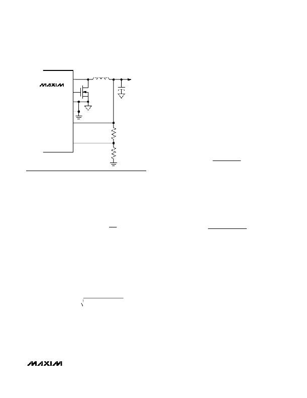
�LX�
�L�
�V� OUT�
�configuration,� choose� a� capacitor� that� has� less� than�
�10°C� temperature� rise� at� the� RMS� input� current� for� opti-�
�mal� reliability� and� lifetime.�
�MAX8550A�
�DL�
�Q2�
�C� OUT�
�Output� Capacitor� Selection� (Buck)�
�PGND1�
�GND�
�OUT�
�FB�
�R� C�
�The� output� filter� capacitor� must� have� low� enough� equiv-�
�alent� series� resistance� (R� ESR� )� to� meet� output� ripple� and�
�load-transient� requirements,� yet� have� high� enough� ESR�
�to� satisfy� stability� requirements.�
�For� processor� core� voltage� converters� and� other� appli-�
�cations� in� which� the� output� is� subject� to� violent� load�
�transients,� the� output� capacitor’s� size� depends� on� how�
�much� R� ESR� is� needed� to� prevent� the� output� from� dip-�
�ping� too� low� under� a� load� transient.� Ignoring� the� sag�
�due� to� finite� capacitance:�
�R� D�
�R� ESR� ≤�
�V� STEP�
�Δ� I� LOAD� (� MAX� )�
�Figure� 6.� Setting� VOUT� with� a� Resistive� Voltage-Divider�
�Find� a� low-loss� inductor� with� the� lowest� possible� DC�
�resistance� that� fits� in� the� allotted� dimensions.� Ferrite�
�cores� are� often� the� best� choice,� although� powdered�
�iron� is� inexpensive� and� can� work� well� at� frequencies� up�
�to� 200kHz.� The� core� must� be� large� enough� not� to� satu-�
�rate� at� the� peak� inductor� current� (I� PEAK� ):�
�In� applications� without� large� and� fast� load� transients,�
�the� output� capacitor’s� size� often� depends� on� how� much�
�R� ESR� is� needed� to� maintain� an� acceptable� level� of� out-�
�put� voltage� ripple.� The� output� ripple� voltage� of� a� step-�
�down� controller� is� approximately� equal� to� the� total�
�inductor� ripple� current� multiplied� by� the� output� capaci-�
�tor’s� R� ESR� .� Therefore,� the� maximum� R� ESR� required� to�
�meet� ripple� specifications� is:�
�I� PEAK� LOAD� (� MAX� )� ?� 1� +�
�=� I�
�?�
�?�
�?�
�LIR� ?�
�2� ?�
�R� ESR� ≤�
�V� RIPPLE�
�I� LOAD� (� MAX� )� � LIR�
�V� OUT� (� V� IN� -� V� OUT� )�
�Most� inductor� manufacturers� provide� inductors� in� stan-�
�dard� values,� such� as� 1.0μH,� 1.5μH,� 2.2μH,� 3.3μH,� etc.�
�Also� look� for� nonstandard� values,� which� can� provide� a�
�better� compromise� in� LIR� across� the� input� voltage� range.�
�If� using� a� swinging� inductor� (where� the� no-load� induc-�
�tance� decreases� linearly� with� increasing� current),� evalu-�
�ate� the� LIR� with� properly� scaled� inductance� values.�
�Input� Capacitor� Selection� (Buck)�
�The� input� capacitor� must� meet� the� ripple� current�
�requirement� (I� RMS� )� imposed� by� the� switching� currents:�
�I� RMS� =� I� LOAD�
�V� IN�
�I� RMS� has� a� maximum� value� of� I� LOAD� /� 2� when� V� IN� =� 2� �
�V� OUT� .� For� most� applications,� nontantalum� capacitors�
�(ceramic,� aluminum,� POS,� or� OSCON)� are� preferred�
�due� to� their� resistance� to� power-up� surge� currents� typi-�
�cal� of� systems� with� a� mechanical� switch� or� connector� in�
�series� with� the� input.� If� the� MAX8550A� is� operated� as�
�the� second� stage� of� a� two-stage� power� conversion� sys-�
�The� actual� capacitance� value� required� relates� to� the�
�physical� size� needed� to� achieve� low� ESR,� as� well� as� to�
�the� chemistry� of� the� capacitor� technology.� Thus,� the�
�capacitor� is� usually� selected� by� ESR� and� voltage� rating�
�rather� than� by� capacitance� value� (this� is� true� of� tanta-�
�lums,� OSCONs,� polymers,� and� other� electrolytics).�
�When� using� low-capacity� filter� capacitors,� such� as�
�ceramic� capacitors,� size� is� usually� determined� by� the�
�capacity� needed� to� prevent� V� SAG� and� V� SOAR� from�
�causing� problems� during� load� transients.� Generally,�
�once� enough� capacitance� is� added� to� meet� the� over-�
�shoot� requirement,� undershoot� at� the� rising� load� edge�
�is� no� longer� a� problem� (see� the� V� SAG� and� V� SOAR� equa-�
�tions� in� the� Transient� Response� section).� However,� low-�
�capacity� filter� capacitors� typically� have� high-ESR� zeros�
�that� can� affect� the� overall� stability� (see� the� Stability�
�Requirements� section).�
�______________________________________________________________________________________�
�19�
�相关PDF资料 |
PDF描述 |
|---|---|
| MAX8632ETI+ | IC PWR SUPPLY DDR 28-TQFN |
| VE-J1B-CZ-B1 | CONVERTER MOD DC/DC 95V 25W |
| ASC15DRAN | CONN EDGECARD 30POS .100 R/A DIP |
| MAX17582GTM+ | IC PWM CTRLR STP-DN DL 48TQFN |
| RMM18DTAS | CONN EDGECARD 36POS R/A .156 SLD |
相关代理商/技术参数 |
参数描述 |
|---|---|
| MAX8550AETI+ | 功能描述:电压模式 PWM 控制器 Integrated DDR Power Supply Solution RoHS:否 制造商:Texas Instruments 输出端数量:1 拓扑结构:Buck 输出电压:34 V 输出电流: 开关频率: 工作电源电压:4.5 V to 5.5 V 电源电流:600 uA 最大工作温度:+ 125 C 最小工作温度:- 40 C 封装 / 箱体:WSON-8 封装:Reel |
| MAX8550AETI+T | 功能描述:电压模式 PWM 控制器 Integrated DDR Power Supply Solution RoHS:否 制造商:Texas Instruments 输出端数量:1 拓扑结构:Buck 输出电压:34 V 输出电流: 开关频率: 工作电源电压:4.5 V to 5.5 V 电源电流:600 uA 最大工作温度:+ 125 C 最小工作温度:- 40 C 封装 / 箱体:WSON-8 封装:Reel |
| MAX8550AETI-T | 功能描述:PMIC 解决方案 RoHS:否 制造商:Texas Instruments 安装风格:SMD/SMT 封装 / 箱体:QFN-24 封装:Reel |
| MAX8550ETI | 功能描述:PMIC 解决方案 RoHS:否 制造商:Texas Instruments 安装风格:SMD/SMT 封装 / 箱体:QFN-24 封装:Reel |
| MAX8550ETI+ | 功能描述:电压模式 PWM 控制器 Integrated DDR Power Supply Solution RoHS:否 制造商:Texas Instruments 输出端数量:1 拓扑结构:Buck 输出电压:34 V 输出电流: 开关频率: 工作电源电压:4.5 V to 5.5 V 电源电流:600 uA 最大工作温度:+ 125 C 最小工作温度:- 40 C 封装 / 箱体:WSON-8 封装:Reel |
发布紧急采购,3分钟左右您将得到回复。