- 您现在的位置:买卖IC网 > PDF目录69035 > MM908E630CVFC (FREESCALE SEMICONDUCTOR INC) MICROCONTROLLER, QCC44 PDF资料下载
参数资料
| 型号: | MM908E630CVFC |
| 厂商: | FREESCALE SEMICONDUCTOR INC |
| 元件分类: | 微控制器/微处理器 |
| 英文描述: | MICROCONTROLLER, QCC44 |
| 封装: | 9 X 9 MM, 1 MM HEIGHT, 0.65 MM PITCH, ROHS COMPLIANT, QFN-44 |
| 文件页数: | 7/48页 |
| 文件大小: | 2299K |
| 代理商: | MM908E630CVFC |
第1页第2页第3页第4页第5页第6页当前第7页第8页第9页第10页第11页第12页第13页第14页第15页第16页第17页第18页第19页第20页第21页第22页第23页第24页第25页第26页第27页第28页第29页第30页第31页第32页第33页第34页第35页第36页第37页第38页第39页第40页第41页第42页第43页第44页第45页第46页第47页第48页
Analog Integrated Circuit Device Data
Freescale Semiconductor
15
908E630
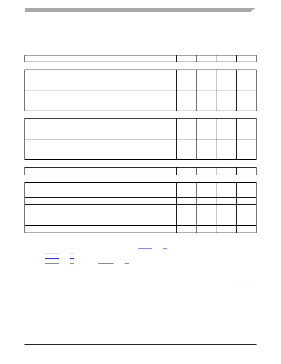
ELECTRICAL CHARACTERISTICS
DYNAMIC ELECTRICAL CHARACTERISTICS
LIN Physical Layer - Driver Characteristics for Normal Slew Rate - 20.0 kBit/sec(47),(48)
Duty Cycle 1: D1 = tBUS_REC(MIN)/(2 X tBIT)
THREC(MAX) = 0.744 X VSUP; THDOM(MAX) = 0.581 X VSUP
7.0 V
≤ VSUP ≤ 18 V, tBIT = 50 s
D1
0.396
Duty Cycle 2: D2 = tBUS_REC(MAX)/(2 x tBIT)
THREC(MIN) = 0.284 x VSUP; THDOM(MIN) = 0.422 x VSUP
7.6 V
≤ VSUP ≤ 18 V, tBIT = 50 s
D2
0.581
Duty Cycle 3: D3 = tBUS_REC(MIN)/(2 x tBIT)
THREC(MAX) = 0.778 x VSUP; THDOM(MAX) = 0.616 x VSUP
7.0 V
≤ VSUP ≤ 18 V, tBIT = 96 s
D3
0.417
Duty Cycle 4: D4 = tBUS_REC(MAX)/(2 x tBIT)
THREC(MIN) = 0.251 x VSUP; THDOM(MIN) = 0.389 x VSUP
7.6 V
≤ VSUP ≤ 18 V, tBIT = 96 s
D4
0.590
LIN PHYSICAL LAYER - DRIVER CHARACTERISTICS FOR FAST SLEW RATE
LIN Fast Slew Rate (Programming Mode)
SRFAST
20
V/
μs
LIN PHYSICAL LAYER - RECEIVER CHARACTERISTICS AND WAKE-UP TIMINGS(47)
tRX_PD
4.2
6.0
μs
tRX_SYM
-2.0
2.0
μs
Bus Wake-up Deglitcher (Sleep and Stop Modes)(50)
tPROPWL
42
70
95
μs
Bus Wake-up Event Reported
From Sleep Mode(51)
From Stop Mode(52)
tWAKE
9.0
27
1500
35
μs
TxD Permanent Dominant State Delay
tTXDDOM
0.65
1.0
1.35
s
Notes
47.
VSUP from 7.0 V to 18 V, bus load RBUS and CBUS 1.0 nF / 1.0 kΩ, 6.8 nF / 660 Ω, 10 nF / 500 Ω. Measurement thresholds: 50% of TxD
signal to LIN signal threshold defined at each parameter. See Figure 6, page 17.
48.
See Figure 7, page 17.
49.
50.
See Figure 9, page 18 for Sleep and Figure 10, page 18 for Stop mode.
51.
The measurement is done with 1.0 F capacitor and 0 mA current load on VDD. The value takes into account the delay to charge the
capacitor. The delay is measured between the bus wake-up threshold (VBUSWU) rising edge of the LIN bus and when VDD reaches 3.0 V.
52.
In Stop mode, the delay is measured between the bus wake-up threshold (VBUSWU) and the falling edge of the IRQ pin. See Figure 10,
Table 4. Dynamic Electrical Characteristics (continued)
All characteristics are for the analog die only. Refer to the 68HC908EY16A datasheet for characteristics of the microcontroller
die. Characteristics noted under conditions 5.5 V
≤ VSUP ≤ 18 V, -40°C ≤ TJ ≤ 125°C, unless otherwise noted. Typical values
noted reflect the approximate parameter mean at TA = 25°C under nominal conditions, unless otherwise noted.
Characteristic
Symbol
Min
Typ
Max
Unit
相关PDF资料 |
PDF描述 |
|---|---|
| MN101CP66DBF | 8-BIT, FLASH, 20 MHz, MICROCONTROLLER, PQFP84 |
| MN101CF66DBF | 8-BIT, FLASH, 20 MHz, MICROCONTROLLER, PQFP84 |
| MN101CF66DAL | 8-BIT, FLASH, 20 MHz, MICROCONTROLLER, PQFP80 |
| MN101CP66DAL | 8-BIT, OTPROM, 20 MHz, MICROCONTROLLER, PQFP80 |
| MN103SA7D | 32-BIT, MROM, MICROCONTROLLER, PQFP80 |
相关代理商/技术参数 |
参数描述 |
|---|---|
| MM-90N | 功能描述:ANT MAGN MNT VEHIC 3.5"DIA 10'NF RoHS:是 类别:RF/IF 和 RFID >> RF 天线 系列:* 标准包装:1 系列:* |
| MM90R9F | 制造商:Ohmite Mfg Co 功能描述: |
| MM912_634 | 制造商:FREESCALE 制造商全称:Freescale Semiconductor, Inc 功能描述:Integrated S12 Based Relay Driver with LIN |
| MM912_634_12 | 制造商:FREESCALE 制造商全称:Freescale Semiconductor, Inc 功能描述:Integrated S12 Based Relay Driver with LIN |
| MM912_637 | 制造商:FREESCALE 制造商全称:Freescale Semiconductor, Inc 功能描述:Xtrinsic Battery Sensor with LIN for 12 V Lead-acid |
发布紧急采购,3分钟左右您将得到回复。