- 您现在的位置:买卖IC网 > PDF目录16215 > SI3225DC0-EVB (Silicon Laboratories Inc)DAUGHTER CARD W/SI3200 INTERFACE PDF资料下载
参数资料
| 型号: | SI3225DC0-EVB |
| 厂商: | Silicon Laboratories Inc |
| 文件页数: | 38/112页 |
| 文件大小: | 0K |
| 描述: | DAUGHTER CARD W/SI3200 INTERFACE |
| 标准包装: | 1 |
| 系列: | ProSLIC® |
| 主要目的: | 接口,模拟前端(AFE) |
| 已用 IC / 零件: | Si3225 |
| 已供物品: | 板,CD |
第1页第2页第3页第4页第5页第6页第7页第8页第9页第10页第11页第12页第13页第14页第15页第16页第17页第18页第19页第20页第21页第22页第23页第24页第25页第26页第27页第28页第29页第30页第31页第32页第33页第34页第35页第36页第37页当前第38页第39页第40页第41页第42页第43页第44页第45页第46页第47页第48页第49页第50页第51页第52页第53页第54页第55页第56页第57页第58页第59页第60页第61页第62页第63页第64页第65页第66页第67页第68页第69页第70页第71页第72页第73页第74页第75页第76页第77页第78页第79页第80页第81页第82页第83页第84页第85页第86页第87页第88页第89页第90页第91页第92页第93页第94页第95页第96页第97页第98页第99页第100页第101页第102页第103页第104页第105页第106页第107页第108页第109页第110页第111页第112页
Si3220/25 Si3200/02
Rev. 1.3
31
Not
Recommended
fo
r N
ew
D
esi
gn
s
3.2. Power Supply Sequencing
Note: This section applies to Si3200 revision E only.
To ensure proper operation, the following power
sequencing guidelines should be followed:
VDD should be allowed to reach its steady state
voltage at least 20 ms before VBATH is allowed to
begin to ramp to its desired voltage.
Transients and oscillations with a dv/dt above 10 V/
s on the VDD and VBATH supplies should always be
avoided.
The ramp-up time for VDD should be in the range of
2 ms to 20 ms. The ramp-up time for VBATH should
be in the range of 10 ms to 150 ms. Slower ramp-up
times are not recommended.
VBATL rail must never be more negative than the
VBATH rail during any part of the power supply ramp-
up.
The Si3200 revision E features an ESD clamp
protection circuit connected between the VDD and
VBATH rails. This clamp protects the Si3200 against
ESD damage when the device is being handled out-of-
circuit during manufacture. Precautions must be taken
in the VDD and VBATH system power supply design. At
power-up, the VDD and VBATH rails must ramp-up from
0 V to their respective target values in a linear fashion
and must not exhibit fast transients or oscillations which
could cause the ESD clamp to be activated for an
extended period of time resulting in damage to the
Si3200. The resistors shown as R20 through R23
together with capacitors C23, C24, C30 and C31 on
Figure 12 and R23 through R26 along with capacitors
C24, C25, C32 and C33 in Figure 13 provide some
measure of protection against in-circuit ESD clamp
activation by forming a filter time constant and by
providing current limiting action in case of momentary
clamp activation during power-up. These resistors and
capacitors must be included in the application circuit,
while ensuring that the VDD and VBATH system power
supplies are designed to exhibit start-up behavior that is
free of undesirable transients or oscillations. Once the
VDD and VBATH are in their steady state final values, the
ESD clamp has circuitry that prevents it from being
activated by transients slower than 10 V/s. In the
steady powered-up state, the VDD and VBATH rails must
therefore not exhibit transients resulting in a voltage
slew rate greater than 10 V/s.
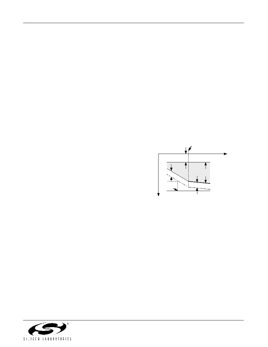
3.3. DC Feed Characteristics
The Si3220 and Si3225 offer programmable constant-
voltage and constant-current operating regions as
illustrated in Figure 14. The constant voltage region
(defined
by
the
open-circuit
voltage,
VOC)
is
programmable from 0 to 63.3 V in 1 V steps. The
constant current region (defined by the loop current
limit, ILIM) is programmable from 18 to 45 mA in
0.87 mA steps. The Si3220 and Si3225 exhibit a
characteristic dc impedance of 640
or 320 during
active mode. (See "3.4. Adaptive Linefeed" on page 34).
The TIP-RING voltage (VOC) is offset from ground by a
programmable voltage (VCM) to provide sufficient
voltage
headroom
to
the
most
positive
terminal
(typically the TIP lead in normal polarity or the RING
lead in reverse polarity) for carrying audio signals. A
similar programmable voltage (VOV) is an offset
between the most negative terminal and the battery
supply rail for carrying audio signals. (See Figure 14.)
The user-supplied battery voltage must have sufficient
amplitude under all operating states to ensure sufficient
headroom. The Si3200/2 may be powered by a lower
secondary battery supply (VBATL) to reduce total power
dissipation when driving short-loop lengths.
Figure 14. DC Linefeed Overhead Voltages
(Forward State)
3.3.1. Calculating Overhead Voltages
The two programmable overhead voltages (VOV and
VCM) represent one portion of the total voltage between
normal operating conditions, these overhead voltages
are sufficiently low to maintain the desired TIP-RING
voltage (VOC). However, there are certain conditions
under which the user must exercise care in providing a
battery supply with enough amplitude to supply the
required TIP-RING voltage and enough margin to
accommodate these overhead voltages. The VCM
voltage is programmed for a given operating condition.
Therefore,
the
open-circuit
voltage
(VOC) varies
according to the required overhead voltage (VOV) and
the supplied battery voltage (VBAT). The user should
pay attention to the maximum VOV and VCM that might
be required for each operating state.
In the off-hook active state, sufficient VOC must be
maintained to correctly power the phone from the
Constant I Region
Constant V Region
V
CM
V
OC
V
OV
V
OV
R
LOOP
V
BATH
V
TIP
V
RING
V
BATL
Secondary V
BAT
Selected
V
Loop Closure Threshold
相关PDF资料 |
PDF描述 |
|---|---|
| SEK220M400ST | CAP ALUM 22UF 400V 20% RADIAL |
| CP2201EK | KIT EVAL FOR CP2201 ETH CTRLR |
| PM1210-820J-RC | INDUCTOR 82UH 5% 1210 SMD |
| H3WWH-6036G | IDC CABLE - HPL60H/AE60G/HPL60H |
| UPS2C471MRD | CAP ALUM 470UF 160V 20% RADIAL |
相关代理商/技术参数 |
参数描述 |
|---|---|
| SI3225DCX-EVB | 功能描述:子卡和OEM板 Si3225 Daughter Card RoHS:否 制造商:BeagleBoard by CircuitCo 产品:BeagleBone LCD4 Boards 用于:BeagleBone - BB-Bone - Open Source Development Kit |
| Si3225-FQ | 功能描述:电信线路管理 IC Dual-Channel SLIC/ codec RoHS:否 制造商:STMicroelectronics 产品:PHY 接口类型:UART 电源电压-最大:18 V 电源电压-最小:8 V 电源电流:30 mA 最大工作温度:+ 85 C 最小工作温度:- 40 C 安装风格:SMD/SMT 封装 / 箱体:VFQFPN-48 封装:Tray |
| SI3225-FQR | 制造商:Silicon Laboratories Inc 功能描述: |
| Si3225-G-FQ | 功能描述:电信线路管理 IC Dual-Channel SLIC codec RoHS:否 制造商:STMicroelectronics 产品:PHY 接口类型:UART 电源电压-最大:18 V 电源电压-最小:8 V 电源电流:30 mA 最大工作温度:+ 85 C 最小工作温度:- 40 C 安装风格:SMD/SMT 封装 / 箱体:VFQFPN-48 封装:Tray |
| SI3225-G-FQR | 功能描述:电信线路管理 IC Dual-CH SLIC/codec Ext Ringing Support RoHS:否 制造商:STMicroelectronics 产品:PHY 接口类型:UART 电源电压-最大:18 V 电源电压-最小:8 V 电源电流:30 mA 最大工作温度:+ 85 C 最小工作温度:- 40 C 安装风格:SMD/SMT 封装 / 箱体:VFQFPN-48 封装:Tray |
发布紧急采购,3分钟左右您将得到回复。