- 您现在的位置:买卖IC网 > PDF目录98141 > SPD6729QCE (INTEL CORP) PCMCIA BUS CONTROLLER, PQFP208 PDF资料下载
参数资料
| 型号: | SPD6729QCE |
| 厂商: | INTEL CORP |
| 元件分类: | 总线控制器 |
| 英文描述: | PCMCIA BUS CONTROLLER, PQFP208 |
| 封装: | MQFP-208 |
| 文件页数: | 41/116页 |
| 文件大小: | 1442K |
| 代理商: | SPD6729QCE |
第1页第2页第3页第4页第5页第6页第7页第8页第9页第10页第11页第12页第13页第14页第15页第16页第17页第18页第19页第20页第21页第22页第23页第24页第25页第26页第27页第28页第29页第30页第31页第32页第33页第34页第35页第36页第37页第38页第39页第40页当前第41页第42页第43页第44页第45页第46页第47页第48页第49页第50页第51页第52页第53页第54页第55页第56页第57页第58页第59页第60页第61页第62页第63页第64页第65页第66页第67页第68页第69页第70页第71页第72页第73页第74页第75页第76页第77页第78页第79页第80页第81页第82页第83页第84页第85页第86页第87页第88页第89页第90页第91页第92页第93页第94页第95页第96页第97页第98页第99页第100页第101页第102页第103页第104页第105页第106页第107页第108页第109页第110页第111页第112页第113页第114页第115页第116页
PD6729 — PCI-to-PC Card (PCMCIA) Controller
30
Datasheet
The PD6729 power can be further managed by controlling socket power as outlined in “Socket
Power Management Features” on page 30. Socket power can be turned on and off through software
or automatically when cards are inserted or removed. The PD6729 provides six pins per socket for
controlling external logic to switch VCC and VPP voltages on and off and for sensing a card’s
operating voltage range. Cards can be turned off when they are not in use.
3.1.6
Socket Power Management Features
Card Removal
When a card is removed from a socket, the PD6729 by default automatically disables the VCC and
VPP supplies to the socket. If Extension Control 1 register bit 1 is a ‘1’, Power Control register
bit 4 is prevented from being automatically cleared when a card is removed. The PD6729 can also
be configured to have management interrupts notify software of card removal.
Card Insertion
At reset, and whenever there is no card in a socket, power to the socket is off. When a card is
detected (card detect input pins, -CD1 and -CD2, to the PD6729 become asserted low), two
independent actions can be programmed to occur.
If the PD6729 has been set for automatic power-on (Power Control register bits 4 and 5 are both
‘1’s), the PD6729 automatically enables the socket VCC supply (and, if so programmed, VPP
supply).
If the PD6729 has been programmed to cause management interrupts for card-detection events,
assertion of -CD1 and -CD2 to the PD6729 causes a management interrupt to be generated to
inform system software that a card was inserted. In the case of manual power detection (Power
Control register bits 5 is a ‘0’), system software can then determine the card’s operating voltage
range and then power-up the socket and initialize the card, or if programmed for automatic power-
on (Power Control register bits 5 is a ‘1’ and Extension Control 1 register bit 1 is a ‘1’), simply
initialize the card.
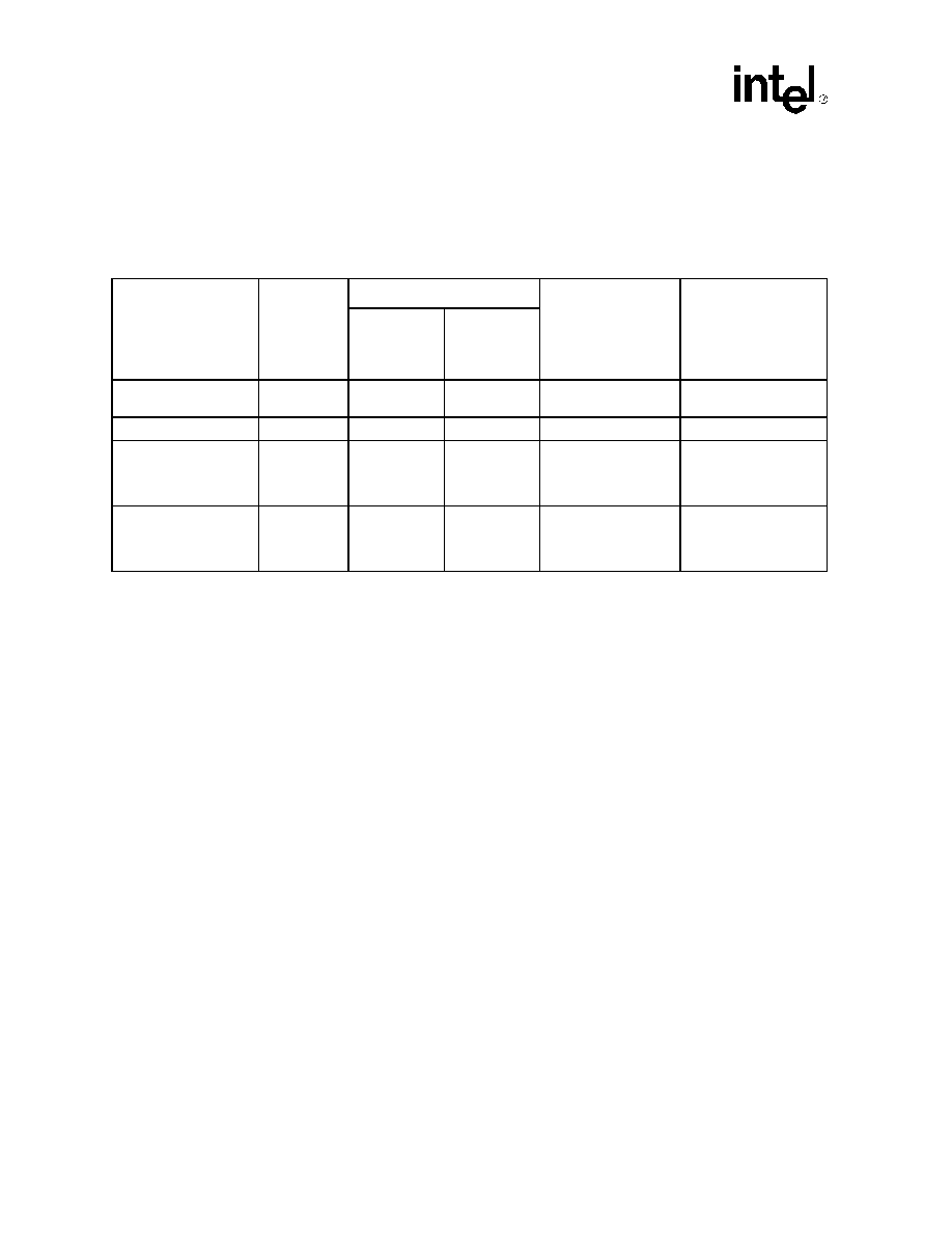
Table 6.
PD6729 Power-Management Modes
Mode Name
RST#
Level
Misc Control 2 Register
Functionality
Typical Power
Consumption
(PCI_VCC = 5.0V,
PCI_K = 33 MHz,
CORE_VDD = 3.3V,
+5V = 5.0V)
Suspend
Mode
(Bit 2)
Low-Power
Dynamic
Mode
(Bit 1)
Low-power Dynamic
(default)
High
0
1
Full functionality
6.4 mW
Normal
High
0
Full functionality
14 mW
Suspend
(software-controlled)
High
1
–
8-bit access to Misc
Control 2 register. No
other register access.
No card in socket(s).
6.4 mW
Reset
Low
––
No register access.
No card in socket(s).
System bus signals
disabled.
21 mW
相关PDF资料 |
PDF描述 |
|---|---|
| SPEAR-09-B042 | 1 CHANNEL(S), 100M bps, I2C BUS CONTROLLER, PBGA289 |
| SPEAR300-2 | 32-BIT, FLASH, 333 MHz, RISC MICROCONTROLLER, PBGA289 |
| SPL505YC264ATT | PROC SPECIFIC CLOCK GENERATOR, PDSO64 |
| SPL505YC264BT | 400 MHz, PROC SPECIFIC CLOCK GENERATOR, PDSO64 |
| SPL505YC264BT | 400 MHz, PROC SPECIFIC CLOCK GENERATOR, PDSO64 |
相关代理商/技术参数 |
参数描述 |
|---|---|
| SPD6730QCB | 制造商:Rochester Electronics LLC 功能描述:- Bulk |
| SPD6832QCB | 制造商:Rochester Electronics LLC 功能描述:- Bulk 制造商:Intel 功能描述: |
| SPD73 | 制造商:未知厂家 制造商全称:未知厂家 功能描述:Shielded Surface Mount Inductors |
| SPD73-103M | 功能描述:固定电感器 10uH 20% .067ohm Shield Choke SMT Pwr RoHS:否 制造商:AVX 电感:10 uH 容差:20 % 最大直流电流:1 A 最大直流电阻:0.075 Ohms 工作温度范围:- 40 C to + 85 C 自谐振频率:38 MHz Q 最小值:40 尺寸:4.45 mm W x 6.6 mm L x 2.92 mm H 屏蔽:Shielded 端接类型:SMD/SMT 封装 / 箱体:6.6 mm x 4.45 mm |
| SPD73-103MTR | 功能描述:固定电感器 10 UH 20% RoHS:否 制造商:AVX 电感:10 uH 容差:20 % 最大直流电流:1 A 最大直流电阻:0.075 Ohms 工作温度范围:- 40 C to + 85 C 自谐振频率:38 MHz Q 最小值:40 尺寸:4.45 mm W x 6.6 mm L x 2.92 mm H 屏蔽:Shielded 端接类型:SMD/SMT 封装 / 箱体:6.6 mm x 4.45 mm |
发布紧急采购,3分钟左右您将得到回复。