参数资料
| 型号: | TMS320DM647ZUT7 |
| 厂商: | Texas Instruments |
| 文件页数: | 15/190页 |
| 文件大小: | 0K |
| 描述: | IC DGTL MEDIA PROC 529-FCBGA |
| 标准包装: | 84 |
| 系列: | TMS320DM64x, DaVinci™ |
| 类型: | 定点 |
| 接口: | 主机接口,I²C,McASP,PCI,SPI,UART |
| 时钟速率: | 720MHz |
| 非易失内存: | ROM(64 kB) |
| 芯片上RAM: | 320kB |
| 电压 - 输入/输出: | 1.8V,3.3V |
| 电压 - 核心: | 1.20V |
| 工作温度: | 0°C ~ 85°C |
| 安装类型: | 表面贴装 |
| 封装/外壳: | 529-BFBGA,FCBGA |
| 供应商设备封装: | 529-FCBGA(19x19) |
| 包装: | 托盘 |
| 其它名称: | 296-34539-5 TMS320DM647ZUT7-ND |
第1页第2页第3页第4页第5页第6页第7页第8页第9页第10页第11页第12页第13页第14页当前第15页第16页第17页第18页第19页第20页第21页第22页第23页第24页第25页第26页第27页第28页第29页第30页第31页第32页第33页第34页第35页第36页第37页第38页第39页第40页第41页第42页第43页第44页第45页第46页第47页第48页第49页第50页第51页第52页第53页第54页第55页第56页第57页第58页第59页第60页第61页第62页第63页第64页第65页第66页第67页第68页第69页第70页第71页第72页第73页第74页第75页第76页第77页第78页第79页第80页第81页第82页第83页第84页第85页第86页第87页第88页第89页第90页第91页第92页第93页第94页第95页第96页第97页第98页第99页第100页第101页第102页第103页第104页第105页第106页第107页第108页第109页第110页第111页第112页第113页第114页第115页第116页第117页第118页第119页第120页第121页第122页第123页第124页第125页第126页第127页第128页第129页第130页第131页第132页第133页第134页第135页第136页第137页第138页第139页第140页第141页第142页第143页第144页第145页第146页第147页第148页第149页第150页第151页第152页第153页第154页第155页第156页第157页第158页第159页第160页第161页第162页第163页第164页第165页第166页第167页第168页第169页第170页第171页第172页第173页第174页第175页第176页第177页第178页第179页第180页第181页第182页第183页第184页第185页第186页第187页第188页第189页第190页
SPRS372H – MAY 2007 – REVISED APRIL 2012
6.10 External Memory Interface A (EMIFA)
The EMIFA can interface to a variety of external devices or ASICs, including:
Pipelined and flow-through synchronous-burst SRAM (SBSRAM)
ZBT (zero bus turnaround) SRAM and late write SRAM
Synchronous FIFOs
Asynchronous memory, including SRAM, ROM, and Flash
6.10.1 EMIFA Device-Specific Information
Timing analysis must be done to verify all ac timing requirements are met. TI recommends utilizing I/O
buffer information specification (IBIS) to analyze all ac timing.
To properly use IBIS models to attain accurate timing analysis for a given system, see the Using IBIS
Models for Timing Analysis Application Report (literature number SPRA839).
To maintain signal integrity, serial termination resistors should be inserted into all EMIFA output signal
lines.
A race condition may exist when certain masters write data to the EMIFA. For example, if master A
passes a software message via a buffer in external memory and does not wait for indication that the write
completes, when master B attempts to read the software message, then the master B read may bypass
the master A write and, thus, master B may read stale data and, therefore, receive an incorrect message.
Some master peripherals (e.g., EDMA3 transfer controllers) will always wait for the write to complete
before signaling an interrupt to the system, thus avoiding this race condition. For masters that do not have
hardware specification of write-read ordering, it may be necessary to specify data ordering via software.
If master A does not wait for indication that a write is complete, it must perform the following workaround:
1. Perform the required write.
2. Perform a dummy write to the EMIFA module ID and revision register.
3. Perform a dummy read to the EMIFA module ID and revision register.
4. Indicate to master B that the data is ready to be read after completion of the read in step 3. The
completion of the read in step 3 ensures that the previous write was done.
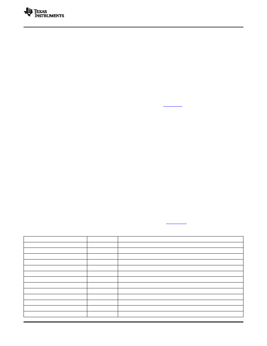
6.10.2 EMIFA Peripheral Register Description(s)
For more information on the EMIF registers shown in Table 6-41, see TMS320DM647/DM648 DSP
External Memory Interface (EMIF) User's Guide (literature number SPRUEK6).
Table 6-41. EMIFA Registers
HEX ADDRESS RANGE
ACRONYM
REGISTER NAME
0x7000 0000
MIDR
Module ID and Revision Register
0x7000 0004
STAT
Status Register
0x7000 0008
-
Reserved
0x7000 000C - 0x7000 001C
-
Reserved
0x7000 0020
BPRIO
Burst Priority Register
0x7000 0024 - 0x7000 004C
-
Reserved
0x7000 0050 - 0x7000 007C
-
Reserved
0x7000 0080
CE2CFG
EMIFA CE2 Configuration Register
0x7000 0084
CE3CFG
EMIFA CE3 Configuration Register
0x7000 0088
-
Reserved
0x7000 008C
-
Reserved
0x7000 0090 - 0x7000 009C
-
Reserved
0x7000 00A0
AWCC
EMIFA Async Wait Cycle Configuration Register
Copyright 2007–2012, Texas Instruments Incorporated
Peripheral Information and Electrical Specifications
111
Product Folder Link(s): TMS320DM647 TMS320DM648
相关PDF资料 |
PDF描述 |
|---|---|
| TMS320VC5409GGU100 | IC DIG SIG PROCESSOR 144-BGA |
| TMS470R1A384PZQ | IC RISC MCU 384K FLASH 100-LQFP |
| TMX320DM365BZCE | IC DIGITAL MEDIA SOC 338NFBGA |
| TMX320F28069UPFPA | IC MCU 32BIT 128KB FLASH 80HTQFP |
| TPS2371PWRG4 | IC PWR INTRFCE SW FOR POE 8TSSOP |
相关代理商/技术参数 |
参数描述 |
|---|---|
| TMS320DM647ZUT9 | 功能描述:数字信号处理器和控制器 - DSP, DSC Dig Media Proc RoHS:否 制造商:Microchip Technology 核心:dsPIC 数据总线宽度:16 bit 程序存储器大小:16 KB 数据 RAM 大小:2 KB 最大时钟频率:40 MHz 可编程输入/输出端数量:35 定时器数量:3 设备每秒兆指令数:50 MIPs 工作电源电压:3.3 V 最大工作温度:+ 85 C 封装 / 箱体:TQFP-44 安装风格:SMD/SMT |
| TMS320DM647ZUTA8 | 功能描述:数字信号处理器和控制器 - DSP, DSC Digital Media Proc RoHS:否 制造商:Microchip Technology 核心:dsPIC 数据总线宽度:16 bit 程序存储器大小:16 KB 数据 RAM 大小:2 KB 最大时钟频率:40 MHz 可编程输入/输出端数量:35 定时器数量:3 设备每秒兆指令数:50 MIPs 工作电源电压:3.3 V 最大工作温度:+ 85 C 封装 / 箱体:TQFP-44 安装风格:SMD/SMT |
| TMS320DM647ZUTD1 | 制造商:Texas Instruments 功能描述:- Trays |
| TMS320DM647ZUTD7 | 功能描述:数字信号处理器和控制器 - DSP, DSC Digital Media Proc RoHS:否 制造商:Microchip Technology 核心:dsPIC 数据总线宽度:16 bit 程序存储器大小:16 KB 数据 RAM 大小:2 KB 最大时钟频率:40 MHz 可编程输入/输出端数量:35 定时器数量:3 设备每秒兆指令数:50 MIPs 工作电源电压:3.3 V 最大工作温度:+ 85 C 封装 / 箱体:TQFP-44 安装风格:SMD/SMT |
| TMS320DM647ZUTD9 | 功能描述:数字信号处理器和控制器 - DSP, DSC Digital Media Proc RoHS:否 制造商:Microchip Technology 核心:dsPIC 数据总线宽度:16 bit 程序存储器大小:16 KB 数据 RAM 大小:2 KB 最大时钟频率:40 MHz 可编程输入/输出端数量:35 定时器数量:3 设备每秒兆指令数:50 MIPs 工作电源电压:3.3 V 最大工作温度:+ 85 C 封装 / 箱体:TQFP-44 安装风格:SMD/SMT |
发布紧急采购,3分钟左右您将得到回复。