- 您现在的位置:买卖IC网 > PDF目录20664 > ZL2004EVK1 (Intersil)KIT EVAL FOR ZL2004 PDF资料下载
参数资料
| 型号: | ZL2004EVK1 |
| 厂商: | Intersil |
| 文件页数: | 16/42页 |
| 文件大小: | 0K |
| 描述: | KIT EVAL FOR ZL2004 |
| 标准包装: | 1 |
| 系列: | * |
第1页第2页第3页第4页第5页第6页第7页第8页第9页第10页第11页第12页第13页第14页第15页当前第16页第17页第18页第19页第20页第21页第22页第23页第24页第25页第26页第27页第28页第29页第30页第31页第32页第33页第34页第35页第36页第37页第38页第39页第40页第41页第42页
�� �
�
�ZL2004�
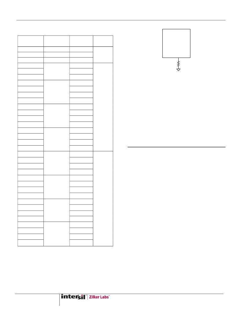
�T� able 11. Soft� Start� Ramp� Settings�
�R� SS�
�LOW�
�OPEN�
�HIGH�
�10� k�
�11� k�
�SS�
�Delay�
�2� ms�
�5� ms�
�10� ms�
�2� ms�
�SS�
�Ramp�
�2� ms�
�5� ms�
�10� ms�
�2� ms�
�5� ms�
�UVLO�
�4.5� V�
�ZL2004�
�R� SS�
�12.1� k�
�10� ms�
�13.3� k�
�2� ms�
�Figure� 12.� SS� Pin� Resistor� Connections�
�14.7� k�
�16.2� k�
�17.8� k�
�19.6� k�
�21.5� k�
�23.7� k�
�26.1� k�
�28.7� k�
�31.6� k�
�34.8� k�
�38.3� k�
�42.2� k�
�46.4� k�
�51.1� k�
�56.2� k�
�61.9� k�
�68.1� k�
�75� k�
�82.5� k�
�90.9� k�
�100� k�
�110� k�
�121� k�
�133� k�
�147� k�
�162� k�
�178� k�
�5� ms�
�10� ms�
�20� ms�
�2� ms�
�5� ms�
�10� ms�
�20� ms�
�5� ms�
�10� ms�
�20� ms�
�2� ms�
�5� ms�
�10� ms�
�20� ms�
�2� ms�
�5� ms�
�10� ms�
�20� ms�
�2� ms�
�5� ms�
�10� ms�
�20� ms�
�2� ms�
�5� ms�
�10� ms�
�20� ms�
�2� ms�
�5� ms�
�10� ms�
�20� ms�
�2� ms�
�5� ms�
�10� ms�
�20� ms�
�4.5� V�
�10.8� V�
�If� the� desired� soft� start� delay� and� ramp� times� are�
�not� one� of� the� values� listed� in� Table� 11� ,� the� times�
�can� be� set� to� a� custom� value� via� the� I� 2� C/SMBus�
�interface.� When� the� SS� delay� time� is� set� to� 0� ms,� the�
�device� will� begin� its� ramp� after� the� internal� circuitry�
�has� initialized� (approx.� 2� ms).� The� soft-start� ramp�
�period� may� be� set� to� values� less� than� 2� ms,� however� it�
�is� generally� recommended� to� set� the� soft-start� ramp� to� a�
�value� greater� than� 500� μs� to� prevent� inadvertent� fault�
�conditions� due� to� excessive� inrush� current.�
�5.5� Power� Good�
�The� ZL2004� provides� a� Power� Good� (PG)� signal� that�
�indicates� the� output� voltage� is� within� a� specified�
�tolerance� of� its� target� level� and� no� fault� condition�
�exists.� By� default,� the� PG� pin� will� assert� if� the� output� is�
�within� -10%/+15%� of� the� target� voltage.� These� limits�
�and� the� polarity� of� the� pin� may� be� changed� via� the�
�I� 2� C/SMBus� interface.� See� Application� Note� AN33� for�
�details.�
�A� PG� delay� period� is� defined� as� the� time� from� when� all�
�conditions� within� the� ZL2004� for� asserting� PG� are� met�
�to� when� the� PG� pin� is� actually� asserted.� This� feature� is�
�commonly� used� instead� of� using� an� external� reset�
�controller� to� control� external� digital� logic.� By� default,�
�the� ZL2004� PG� delay� is� set� equal� to� the� soft-start� ramp�
�time� setting.� Therefore,� if� the� soft-start� ramp� time� is� set�
�to� 10� ms,� the� PG� delay� will� be� set� to� 10� ms.� The� PG�
�delay� may� be� set� independently� of� the� soft-start� ramp�
�using� the� I� 2� C/SMBus� as� described� in� Application� Note�
�AN33.�
�The� value� of� this� resistor� is� measured� upon� start-up� or�
�Restore� and� will� not� change� if� the� resistor� is� varied�
�after� power� has� been� applied� to� the� ZL2004.� See�
��16�
�FN6846.3�
�February� 15,� 2011�
�相关PDF资料 |
PDF描述 |
|---|---|
| TTN0.63SV | 5/8" THERMASHIELD TUBE SLV 250' |
| TC1304-ZA0EMF | IC REG DL BUCK/LINEAR SYNC 10DFN |
| ESC10DRTH | CONN EDGECARD 20POS DIP .100 SLD |
| ISL6425EVAL2 | EVAL BOARD 2 FOR ISL6425 |
| ISL59532IK-EVAL | EVAL BOARD FOR ISL59532 |
相关代理商/技术参数 |
参数描述 |
|---|---|
| ZL2005 | 制造商:INTERSIL 制造商全称:Intersil Corporation 功能描述:Digital-DC? Integrated Power Management and Conversion IC |
| ZL2005ALNF | 制造商:Intersil Corporation 功能描述:DIGITAL DC-DC CONTROLLER W/ DRIVERS - TRAY100 - Trays 制造商:Intersil Corporation 功能描述:IC REG CNTRLR BUCK PWM 36-QFN 制造商:Intersil Corporation 功能描述:Digital DC-DC Controller w/ Drivers - BULK 50 |
| ZL2005ALNFT | 功能描述:电压模式 PWM 控制器 DIGTL DC-DC CNTRLR W/DRVRS TR100 RoHS:否 制造商:Texas Instruments 输出端数量:1 拓扑结构:Buck 输出电压:34 V 输出电流: 开关频率: 工作电源电压:4.5 V to 5.5 V 电源电流:600 uA 最大工作温度:+ 125 C 最小工作温度:- 40 C 封装 / 箱体:WSON-8 封装:Reel |
| ZL2005ALNFT1 | 功能描述:电压模式 PWM 控制器 DIGTL DC-DC CNTRLR W/DRVRS TR1K RoHS:否 制造商:Texas Instruments 输出端数量:1 拓扑结构:Buck 输出电压:34 V 输出电流: 开关频率: 工作电源电压:4.5 V to 5.5 V 电源电流:600 uA 最大工作温度:+ 125 C 最小工作温度:- 40 C 封装 / 箱体:WSON-8 封装:Reel |
| ZL2005P | 制造商:INTERSIL 制造商全称:Intersil Corporation 功能描述:Digital-DC? Controller with Drivers and POLA/DOSA Trim |
发布紧急采购,3分钟左右您将得到回复。