- 您现在的位置:买卖IC网 > PDF目录16915 > ADP1043A-USB-Z (Analog Devices Inc)EVAL BOARD DIG POWER SUPPLY PDF资料下载
参数资料
| 型号: | ADP1043A-USB-Z |
| 厂商: | Analog Devices Inc |
| 文件页数: | 23/72页 |
| 文件大小: | 0K |
| 描述: | EVAL BOARD DIG POWER SUPPLY |
| 标准包装: | 1 |
| 附件类型: | 连接 USB 至 I2C 的接收器 |
| 适用于相关产品: | ADP1043A |
| 相关产品: | ADP1043AACPZ-RLDKR-ND - IC SECONDARY SIDE CTRLR 32LFCSP ADP1043AACPZ-RLCT-ND - IC SECONDARY SIDE CTRLR 32LFCSP ADP1043AACPZ-RLTR-ND - IC SECONDARY SIDE CTRLR 32LFCSP |
第1页第2页第3页第4页第5页第6页第7页第8页第9页第10页第11页第12页第13页第14页第15页第16页第17页第18页第19页第20页第21页第22页当前第23页第24页第25页第26页第27页第28页第29页第30页第31页第32页第33页第34页第35页第36页第37页第38页第39页第40页第41页第42页第43页第44页第45页第46页第47页第48页第49页第50页第51页第52页第53页第54页第55页第56页第57页第58页第59页第60页第61页第62页第63页第64页第65页第66页第67页第68页第69页第70页第71页第72页
�� �
�
�ADP1043A�
�CS2� Pin�
�The� user� sets� the� full-scale� (FS)� voltage� drop—37.5� mV,�
�75� mV,� or� 150� mV—that� is� present� across� the� R� SENSE� resistor�
�by� programming� Register� 0x23,� Bits[7:6].�
�The� CS2� ADC� has� an� input� range� of� 250� mV.� The� resolution� is�
�12� bits,� which� means� that� the� LSB� size� is� 250� mV/4096� =� 61.04� μV.�
�The� user� is� limited� to� an� input� range� of� 215� mV.�
�The� equation� to� calculate� the� ADC� code� at� a� certain� voltage�
�(V� X� )� is� given� by� the� following� formula:�
�ADC� Code� =� V� X� /250� mV� � 4096�
�For� example,� when� there� is� 150� mV� on� the� input� of� the� ADC�
�ADC� Code� =� 150� mV/250� mV� � 4096�
�ADC� Code� =� 2457�
�Therefore,� to� convert� the� CS2� value� reading� to� a� real� current,�
�use� the� following� formula:�
�I� OUT� =� (� CS2_Value� /2457)� � (� FS� /� R� SENSE� )�
�where:�
�FS� is� the� full-scale� voltage� drop� (37.5� mV,� 75� mV,� or� 150� mV).�
�R� SENSE� is� the� sense� resistor� value.�
�For� example,� if� CS2_Value� =� 1520,� R� SENSE� =� 20� mΩ,� and�
�FS� =� 150� mV,� the� real� current� is� calculated� as� follows:�
�I� OUT� =� (1520/2457)� ×� (150� mV/20� mΩ)�
�FIRST� FLAG� FAULT� ID� AND� VALUE� REGISTERS�
�When� the� ADP1043A� registers� several� fault� conditions,� it� stores�
�the� value� of� the� first� fault� in� a� dedicated� register.� For� example,� if�
�the� overtemperature� (OTP)� fault� is� registered,� followed� by� an�
�OVP� fault,� the� OTP� flag� is� stored� in� the� first� flag� ID� register�
�(Register� 0x10).� This� register� gives� the� user� more� information�
�for� fault� diagnosis� than� a� simple� flag.� The� contents� of� this� register�
�are� latched,� meaning� that� they� are� stored� until� read� by� the� user.�
�The� contents� are� also� reset� by� a� PSON� signal.�
�If� a� flag� is� set� to� be� ignored,� it� does� not� appear� in� the� first� flag�
�register.�
�EXTERNAL� FLAG� INPUT� (FLAGIN� PIN)�
�The� FLAGIN� pin� can� be� used� to� send� an� external� fault�
�signal� into� the� ADP1043A.� The� reaction� to� this� flag� can�
�be� programmed� in� the� same� way� as� the� internal� flags.�
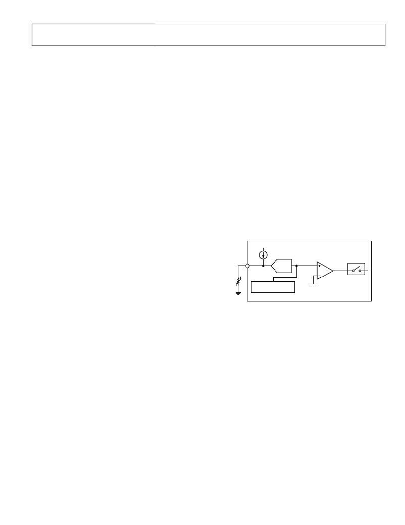
�TEMPERATURE� READINGS� (RTD� PIN)�
�The� RTD� pin� is� set� up� for� use� with� an� external� 100� k� negative�
�temperature� coefficient� (NTC)� thermistor.� The� RTD� pin� has� an�
�internal� 10.8� μA� current� source.� Therefore,� with� a� 100� kΩ� therm-�
�istor,� the� voltage� on� the� RTD� pin� is� 1� V� at� 25°C.� An� ADC� on� the�
�ADP1043A� monitors� the� voltage� on� the� RTD� pin.�
�10μA�
�I� OUT� =� 4.64� A�
�POWER� READINGS�
�The� output� power� value� register� (Register� 0x19)� is� the� product�
�of� the� VS3� voltage� value� and� the� CS2� current� value.� Therefore,�
�100k� ?�
�NTC�
�RTD�
�RTD�
�ADC�
�RTD� TEMPERATURE�
�VALUE� REGISTER�
�REG� 0x1A[15:4]�
�OTP�
�THRESHOLD�
�REG� 0x2F[7:0]�
�OTP�
�FLAG�
�FLAGS�
�a� combination� of� the� formulas� in� the� Voltage� Readings� section�
�and� the� CS2� Pin� section� is� used� to� calculate� the� power� reading�
�in� watts.� This� register� is� a� 16-bit� word.� It� multiplies� two� 12-bit�
�numbers� and� discards� the� eight� LSBs.�
�P� OUT� =� (� V� OUT� )� � (� I� OUT� )�
�For� example,�
�P� OUT� =� (12� V)� � (4.64� A)� =� 55.68� W�
�POWER� MONITORING� ACCURACY�
�The� ADP1043A� power� monitoring� accuracy� is� specified� relative�
�to� the� full-scale� range� of� the� signal� that� it� is� measuring.�
�Figure� 28.� RTD� Pin� Internal� Details�
�The� output� of� the� RTD� ADC� is� linearly� proportional� to� the�
�voltage� on� the� RTD� pin.� However,� thermistors� exhibit� a� non-�
�linear� function� of� resistance� vs.� temperature.� Therefore,� it� is�
�necessary� to� perform� some� postprocessing� on� the� RTD� ADC�
�reading� to� accurately� read� the� temperature.� This� postprocessing�
�can� be� in� the� form� of� a� lookup� table� or� polynomial� equation� to�
�match� the� specific� NTC� being� used.�
�OVERTEMPERATURE� PROTECTION� (OTP)�
�If� the� temperature� sensed� at� the� RTD� pin� exceeds� the� program-�
�mable� threshold,� the� OTP� flag� is� set.� The� hysteresis� on� this� flag�
�is� 16� mV� (see� Register� 0x2F� in� Table� 43� for� details).� The� response�
�to� the� OTP� flag� is� programmable.�
�The� RTD� trim� is� required� to� make� accurate� temperature� readings�
�at� the� lower� end� of� the� RTD� ADC� range.� This� results� in� a� more�
�accurate� measurement� for� determining� the� OTP� threshold� (see�
�the� RTD/OTP� Trim� section).�
�Rev.� 0� |� Page� 23� of� 72�
�相关PDF资料 |
PDF描述 |
|---|---|
| VE-2TZ-EX | CONVERTER MOD DC/DC 2V 30W |
| GCM15DTAS | CONN EDGECARD 30POS R/A .156 SLD |
| 202D232-4-61/42-0 | BOOT MOLDED |
| VE-2TZ-EW | CONVERTER MOD DC/DC 2V 40W |
| GSM06DREF | CONN EDGECARD 12POS .156 EYELET |
相关代理商/技术参数 |
参数描述 |
|---|---|
| ADP1043-EVALZ | 制造商:Analog Devices 功能描述:EVALUATION BOARDS - Bulk |
| ADP1043FB100-EVALZ | 制造商:Analog Devices 功能描述:ADP1043 100W EVALUATION BOARD |
| ADP1045ACPZ-RL | 制造商:Analog Devices 功能描述: |
| ADP1046 | 制造商:AD 制造商全称:Analog Devices 功能描述:Digital Controller for Isolated |
| ADP1046-100-EVALZ | 功能描述:BOARD EVAL FOR ADP1046-100 RoHS:是 类别:编程器,开发系统 >> 评估演示板和套件 系列:- 标准包装:1 系列:PCI Express® (PCIe) 主要目的:接口,收发器,PCI Express 嵌入式:- 已用 IC / 零件:DS80PCI800 主要属性:- 次要属性:- 已供物品:板 |
发布紧急采购,3分钟左右您将得到回复。