- 您现在的位置:买卖IC网 > PDF目录16264 > DS21Q59DK (Maxim Integrated Products)KIT DESIGN FOR DS21Q59 PDF资料下载
参数资料
| 型号: | DS21Q59DK |
| 厂商: | Maxim Integrated Products |
| 文件页数: | 50/76页 |
| 文件大小: | 0K |
| 描述: | KIT DESIGN FOR DS21Q59 |
| 产品培训模块: | Lead (SnPb) Finish for COTS Obsolescence Mitigation Program |
| 标准包装: | 1 |
| 主要目的: | 电信,调帧器和线路接口装置(LIU) |
| 已用 IC / 零件: | DS21Q59 |
第1页第2页第3页第4页第5页第6页第7页第8页第9页第10页第11页第12页第13页第14页第15页第16页第17页第18页第19页第20页第21页第22页第23页第24页第25页第26页第27页第28页第29页第30页第31页第32页第33页第34页第35页第36页第37页第38页第39页第40页第41页第42页第43页第44页第45页第46页第47页第48页第49页当前第50页第51页第52页第53页第54页第55页第56页第57页第58页第59页第60页第61页第62页第63页第64页第65页第66页第67页第68页第69页第70页第71页第72页第73页第74页第75页第76页
DS21Q59 Quad E1 Transceiver
54 of 76
23.
INTERLEAVED PCM BUS OPERATION
In many architectures, the PCM outputs of individual framers are combined into higher-speed PCM buses to
simplify transport across the system backplane. The DS21Q59 can be configured to allow PCM data buses to be
multiplexed into higher-speed data buses, eliminating external hardware and saving board space and cost. The
DS21Q59 uses a channel interleave method. See Figure 24-4 and Figure 24-7 for details of the channel interleave.
The interleaved PCM bus option supports three bus speeds. The 4.096MHz bus speed allows two PCM data
streams to share a common bus. The 8.192MHz bus speed allows four PCM data streams to share a common bus.
The 16.384MHz bus speed allows eight PCM data streams to share a common bus. See Figure 23-1 for an
example of four transceivers sharing a common 8.192MHz PCM bus. The receive elastic stores of each transceiver
must be enabled. Through the IBO register the user can configure each transceiver for a specific bus speed and
position. For all IBO bus configurations each transceiver is assigned an exclusive position in the high-speed PCM
bus. When the device is configured for IBO operation, the TSYNCx pin should be configured as an output or as an
input connected to ground. The user cannot supply a TSYNCx signal in this mode. When IBO operation is enabled,
TSYNCx will be internally tied to RSYNCx. If TSYNCx is configured as an input, the physical pin will be
disconnected from the internal TSYNCx signal and should therefore be connected to ground to keep it from
floating.
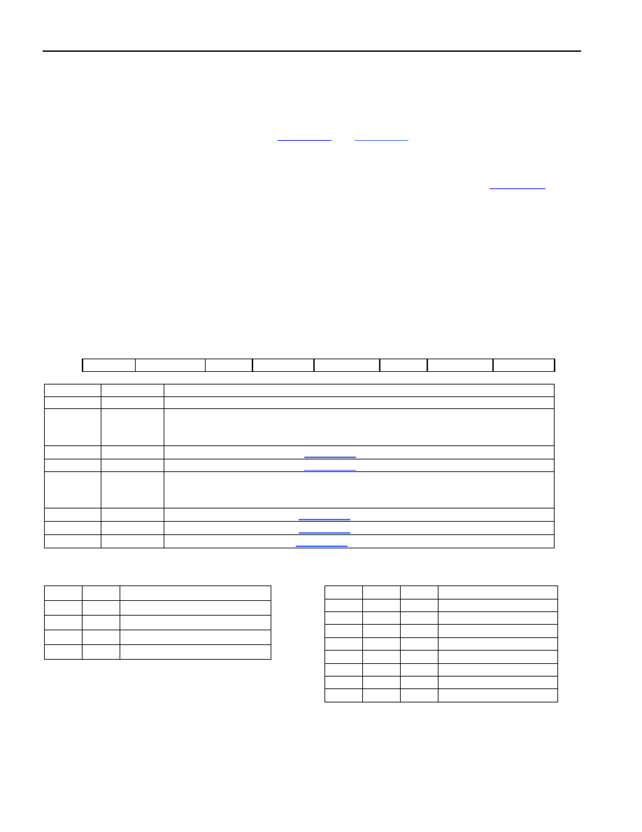
Register Name:
IBO
Register Description:
Interleave Bus Operation Register
Register Address:
1C Hex
Bit #
7
6
5
4
3
2
1
0
Name
—
IBOTCS
SCS1
SCS0
IBOEN
DA2
DA1
DA0
NAME
BIT
FUNCTION
—
7
Not Assigned. Should be set to 0.
IBOTCS
6
IBO Transmit Clock Source
0 = TCLK pin is the source of transmit clock
1 = Transmit clock is internally derived from the clock at the SYSCLK pin
SCS1
5
System Clock Select Bit 1 (Table 23-A)
SCS0
4
System Clock Select Bit 0 (Table 23-A)
IBOEN
3
Interleave Bus Operation Enable
0 = IBO disabled
1 = IBO enabled
DA2
2
Device Assignment Bit 3 (Table 23-B)
DA1
1
Device Assignment Bit 2 (Table 23-B)
DA0
0
Device Assignment Bit 1(Table 23-B)
Table 23-A. IBO System Clock Select
SCS1
SCS0
FUNCTION
0
2.048MHz, single device on bus
0
1
4.096MHz, two devices on bus
1
0
8.192MHz, four devices on bus
1
16.384MHz, eight devices on bus
Table 23-B. IBO Device Assignment
DA2
DA1
DA0
FUNCTION
0
1st device on bus
0
1
2nd device on bus
0
1
0
3rd device on bus
0
1
4th device on bus
1
0
5th device on bus
1
0
1
6th device on bus
1
0
7th device on bus
1
8th device on bus
相关PDF资料 |
PDF描述 |
|---|---|
| RCM28DCTH | CONN EDGECARD 56POS DIP .156 SLD |
| EET-ED2D152EA | CAP ALUM 1500UF 200V 20% SNAP |
| RCM28DCTD | CONN EDGECARD 56POS DIP .156 SLD |
| PLE0G681MDO1 | CAP ALUM 680UF 4V 20% RADIAL |
| PLE0E561MCO1 | CAP ALUM 560UF 2.5V 20% RADIAL |
相关代理商/技术参数 |
参数描述 |
|---|---|
| DS21Q59L | 功能描述:网络控制器与处理器 IC Quad E1 Transceiver RoHS:否 制造商:Micrel 产品:Controller Area Network (CAN) 收发器数量: 数据速率: 电源电流(最大值):595 mA 最大工作温度:+ 85 C 安装风格:SMD/SMT 封装 / 箱体:PBGA-400 封装:Tray |
| DS21Q59L+ | 功能描述:网络控制器与处理器 IC Quad E1 Transceiver RoHS:否 制造商:Micrel 产品:Controller Area Network (CAN) 收发器数量: 数据速率: 电源电流(最大值):595 mA 最大工作温度:+ 85 C 安装风格:SMD/SMT 封装 / 箱体:PBGA-400 封装:Tray |
| DS21Q59LN | 功能描述:网络控制器与处理器 IC Quad E1 Transceiver RoHS:否 制造商:Micrel 产品:Controller Area Network (CAN) 收发器数量: 数据速率: 电源电流(最大值):595 mA 最大工作温度:+ 85 C 安装风格:SMD/SMT 封装 / 箱体:PBGA-400 封装:Tray |
| DS21Q59LN+ | 功能描述:网络控制器与处理器 IC Quad E1 Transceiver RoHS:否 制造商:Micrel 产品:Controller Area Network (CAN) 收发器数量: 数据速率: 电源电流(最大值):595 mA 最大工作温度:+ 85 C 安装风格:SMD/SMT 封装 / 箱体:PBGA-400 封装:Tray |
| DS21S07A | 制造商:Maxim Integrated Products 功能描述: |
发布紧急采购,3分钟左右您将得到回复。