- 您现在的位置:买卖IC网 > PDF目录295865 > E28F200B5B60 (INTEL CORP) DIRECTIONAL COUPLER, 20DB, SMT PDF资料下载
参数资料
| 型号: | E28F200B5B60 |
| 厂商: | INTEL CORP |
| 元件分类: | PROM |
| 英文描述: | DIRECTIONAL COUPLER, 20DB, SMT |
| 中文描述: | 256K X 8 FLASH 5V PROM, 70 ns, PDSO48 |
| 封装: | 12 X 20 MM, TSOP-48 |
| 文件页数: | 8/44页 |
| 文件大小: | 345K |
| 代理商: | E28F200B5B60 |
第1页第2页第3页第4页第5页第6页第7页当前第8页第9页第10页第11页第12页第13页第14页第15页第16页第17页第18页第19页第20页第21页第22页第23页第24页第25页第26页第27页第28页第29页第30页第31页第32页第33页第34页第35页第36页第37页第38页第39页第40页第41页第42页第43页第44页
28F200B5, 28F004/400B5, 28F800B5
E
16
PRELIMINARY
3.2
Modes of Operation
The flash memory has three read modes and two
write modes. The read modes are read array, read
identifier, and read status. The write modes are
program and block erase. An additional mode,
erase suspend to read, is available only during
block erasures. These modes are reached using
the
commands
summarized
in
Table 6.
A
comprehensive chart showing the state transitions
is in Appendix A.
3.2.1
READ ARRAY
After initial device power-up or return from deep
power-down mode, the device defaults to read
array mode. This mode can also be entered by
writing the Read Array command (FFH). The device
remains in this mode until another command is
written.
Data is read by presenting the address of the read
location in conjunction with a read bus operation.
Once the WSM has started a program or block
erase operation, the device will not recognize the
Read Array command until the WSM completes its
operation unless the WSM is suspended via an
Erase
Suspend
command.
The
Read
Array
command functions independently of the VPP
voltage and RP# can be VIH or VHH.
During system design, consideration should be
taken to ensure address and control inputs meet
required input slew rates of <10 ns as defined in
Figures 11 and 12.
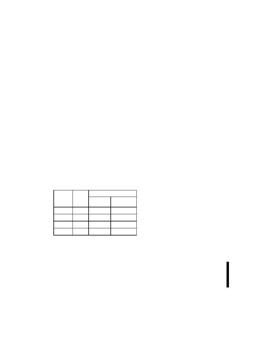
Table 5. Intelligent Identifier Codes
Product
Mfr. ID
Device ID
-T
Top Boot
-B
Bottom Boot
28F004
89H
78H
79H
28F200
0089 H
2274 H
2275 H
28F400
0089 H
4470 H
4471 H
28F800
0089 H
889C H
889D H
NOTE:
In byte-mode, the upper byte will be tri-stated.
3.2.2
READ IDENTIFIER
To read the manufacturer and device codes, the
device must be in intelligent identifier read mode,
which can be reached using two methods: by
writing the intelligent identifier command (90H) or
by taking the A9 pin to VID. Once in intelligent
identifier
read
mode,
A0
=
0
outputs
the
manufacturer’s identification code and A0 = 1
outputs the device code. In byte-wide mode, only
the lower byte of the above signatures is read
(DQ15/A–1 is a “don’t care” in this mode). See
Table 5 for product signatures. To return to read
array mode, write a Read Array command (FFH).
3.2.3
READ STATUS REGISTER
The status register indicates when a program or
erase operation is complete, and the success or
failure of that operation. The status register is
output when the device is read in read status
register mode, which can be entered by issuing the
Read Status (70H) command to the CUI. This mode
is automatically entered when a program or erase
operation is initiated, and the device remains in this
mode after the operation has completed. Status
register bit codes are defined in Table 8.
The status register bits are output on DQ0–DQ7, in
both byte-wide (x8) or word-wide (x16) mode. In the
word-wide mode, the upper byte, DQ8–DQ15,
outputs 00H during a Read Status command. In the
byte-wide mode, DQ8–DQ14 are tri-stated and
DQ15/A–1 retains the low order address function.
Note that the contents of the status register are
latched on the falling edge of OE# or CE#,
whichever occurs last in the read cycle. This
prevents possible bus errors which might occur if
status register contents change while being read.
CE# or OE# must be toggled with each subsequent
status read, or the status register will not indicate
completion of a program or erase operation.
Issue a Read Array (FFH) command to return to
read array.
3.2.3.1
Clearing the Status Register
Status register bits SR.5, SR.4, and SR.3 are set to
“1”s when appropriate by the WSM but can only be
reset by the Clear Status Register command.
These bits indicate various failure conditions (see
Table 8). By requiring system software to reset
相关PDF资料 |
PDF描述 |
|---|---|
| E28F200BX-B120 | 2-MBIT (128K x 16, 256K x 8) BOOT BLOCK FLASH MEMORY FAMILY |
| E28F200BX-B60 | 2-MBIT (128K x 16, 256K x 8) BOOT BLOCK FLASH MEMORY FAMILY |
| E28F200BX-B80 | 2-MBIT (128K x 16, 256K x 8) BOOT BLOCK FLASH MEMORY FAMILY |
| E28F200BX-T120 | 2-MBIT (128K x 16, 256K x 8) BOOT BLOCK FLASH MEMORY FAMILY |
| E28F002BX-T120 | 2-MBIT (128K x 16, 256K x 8) BOOT BLOCK FLASH MEMORY FAMILY |
相关代理商/技术参数 |
参数描述 |
|---|---|
| E28F200B5B80 | 制造商:INTEL 制造商全称:Intel Corporation 功能描述:SMART 5 BOOT BLOCK FLASH MEMORY FAMILY 2, 4, 8 MBIT |
| E28F200B5T60 | 制造商:INTEL 制造商全称:Intel Corporation 功能描述:SMART 5 BOOT BLOCK FLASH MEMORY FAMILY 2, 4, 8 MBIT |
| E28F200B5T80 | 制造商:Rochester Electronics LLC 功能描述:- Bulk 制造商:Intel 功能描述: |
| E28F200BL-B150 | 制造商:INTEL 制造商全称:Intel Corporation 功能描述:2-MBIT (128K x 16, 256K x 8)LOW-POWER BOOT BLOCK FLASH MEMORY FAMILY |
| E28F200BL-T150 | 制造商:INTEL 制造商全称:Intel Corporation 功能描述:2-MBIT (128K x 16, 256K x 8)LOW-POWER BOOT BLOCK FLASH MEMORY FAMILY |
发布紧急采购,3分钟左右您将得到回复。