- 您现在的位置:买卖IC网 > PDF目录67672 > GP2021 (Mitel Networks Corporation) GPS 12 channel Correlator Advance Information PDF资料下载
参数资料
| 型号: | GP2021 |
| 厂商: | Mitel Networks Corporation |
| 英文描述: | GPS 12 channel Correlator Advance Information |
| 中文描述: | 全球定位系统12通道相关器研究进展信息 |
| 文件页数: | 3/62页 |
| 文件大小: | 372K |
| 代理商: | GP2021 |
第1页第2页当前第3页第4页第5页第6页第7页第8页第9页第10页第11页第12页第13页第14页第15页第16页第17页第18页第19页第20页第21页第22页第23页第24页第25页第26页第27页第28页第29页第30页第31页第32页第33页第34页第35页第36页第37页第38页第39页第40页第41页第42页第43页第44页第45页第46页第47页第48页第49页第50页第51页第52页第53页第54页第55页第56页第57页第58页第59页第60页第61页第62页
11
GP2021
Epoch Counter
The Epoch Counters keep track of the number of code
periods over a 1 second interval. This is represented by a 5 bit
word for the number of 1 ms integration periods (0 to 19), plus
a 6 bit word containing the number of 20 ms counts (0 to 49).
The Epoch Counters can be pre–loaded to synchronise them
to the data stream coming from the satellite. This value will be
transferred immediately to the counter when in Update mode,
or after the next TIC if in PRESET Mode.
The Epoch Counter values are latched on each TIC into the
CHx_EPOCH register. In addition the instantaneous values
are available from the CHx_EPOCH_CHECK register.
PERIPHERAL FUNCTIONS
The following section describes the Dual UART, Real
Time Clock and Watchdog, Power and Reset Control and
Discrete I/O blocks.
Dual UART
A Dual UART is included for serial communications. It has
2 identical blocks, UART_A and UART_B, each containing
separate transmit and receive channels. The parity and
separate transmit and receive baud rate can be configured
independently for each UART. Each uses a polled processor
interface and each transmit and receive channel has an 8 byte
deep FIFO.
For further information on the UART registers refer to the
Detailed Description of Registers and the GP2021 Register
Map.
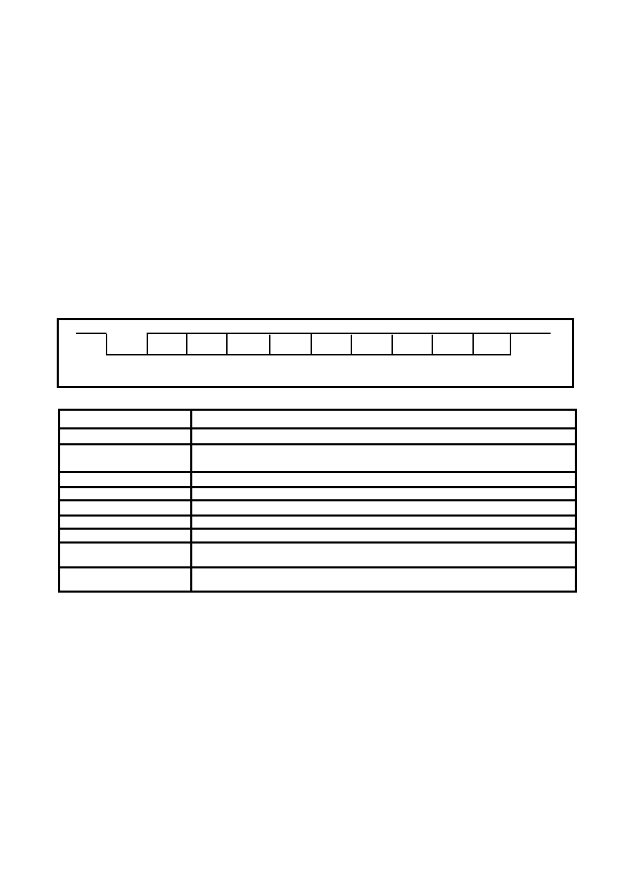
A typical serial data stream is shown in Fig. 6. The Parity
bit is optional and if no parity is selected the time slot for it is
removed from the data stream and the Stop bit follows
immediately after the last data bit in both transmit and receive
directions. Note that the LSB is always preceded by a Start bit.
Table
3
shows
possible
UART
configurations.
Last
Start
D8
D9
D10
D11
D12
D13
D14
D15
P
Stop
First
LSB
MSB
Parity
(optional)
Fig. 6 Serial Data waveform
Parameter
Value
Start bits
1 bit Low
Data bits
8 bits
Logic 0 = Low
Logic 1 = High
Stop bits
1 bit High
Parity
Odd/Even/None
Flow control
None
Transmit FIFO depth
8 bytes
Receive FIFO depth
8 bytes
FIFO speed
Transmit FIFO write rate and Receive FIFO read rate maximum is one byte per 230ns.
The maximum buffer through delay is 2
s.
Data rate
300, 600,1.2k, 2.4k, 4.8k, 9.6k, 19.2k, 38.4k and 76.8k baud. Transmit and Receive
rates individu-ally configured.
Table 3 UART Functionality
Receiver
The incoming data streams on RXA, RXB are sampled by
a clock at nominally 20 times the data rate, to search for an
incoming Start bit. Once the receiver is synchronised to the
data stream, each data bit is sampled only at its nominal centre
to avoid errors due to slow or noisy bit edges. The receiver will
resynchronise to each Start bit to prevent the accumulation of
phase errors.
Only valid data (having correct Start, Stop and Parity bits)
will be stored in the receiver FIFO. If a received word contains
a parity or framing (Start/Stop bit) error, the appropriate flag bit
will be set in the status register. If too many valid data words
are received for the FIFO to hold, the excess will not be written
into the FIFO, and an Overflow bit will be set in the status
register. When receiving a continuous transmission, the Start
bit of one word will follow immediately after the Stop bit of the
preceding word. At lower word rates, a High is expected
between words. The receiver will accept data with a baud rate
error of up to
±1%.
Transmitter
Data is transmitted on pins TXA and TXB. In continuous
transmission, the Start bit of one word will follow immediately
after the Stop bit of the preceding word. At lower word rates,
a High is sent between words.
If too many data words are written by the microprocessor
to the UART for the transmitter FIFO to hold, the excess will not
be stored. The UART will resume normal operation as soon as
space becomes available. To avoid data loss, the software
should limit the transmit data rate by either: keeping track of
the number of bytes sent and the time to transmit them, or
should read the Status register and stop writing when the Full
bit is set.
相关PDF资料 |
PDF描述 |
|---|---|
| GRM40Y5V105Z16 | Circular Connector; MIL SPEC:MIL-C-26482, Series I, Solder; Body Material:Aluminum; Series:PT06; No. of Contacts:21; Connector Shell Size:22; Connecting Termination:Solder; Circular Shell Style:Straight Plug; Body Style:Straight |
| GRM42-6X5R475K10 | 50/100M SOT-23 CMOS RF LDO REGULATORS |
| GT- 32090 | Highly Integrated Single-Chip System Controller(高集成单片系统控制器) |
| GT-48001A | Switched Ethernet Controller For 10BaseX(10BaseX交换式快速以太网控制器) |
| GT-48002A | Switched Fast Ethernet Controller for 100BaseX(100BaseX交换式快速以太网控制器) |
相关代理商/技术参数 |
参数描述 |
|---|---|
| GP2021IGGQ1R | 制造商:未知厂家 制造商全称:未知厂家 功能描述:Correlator |
| GP202K | 制造商:GTM 制造商全称:GTM 功能描述:SURFACE MOUNT,SWITCHING DIODE |
| GP2030S | 制造商:GTM 制造商全称:GTM 功能描述:N AND P-CHANNEL ENHANCEMENT MODE POWER MOSFET |
| GP2-031X250-50 | 制造商:GROOV-PIN 功能描述: |
| GP204 | 制造商:DEC 制造商全称:DEC 功能描述:2 AMP SOFT GLASS PASSIVATED DIODES |
发布紧急采购,3分钟左右您将得到回复。