- 您现在的位置:买卖IC网 > PDF目录67672 > GP2021 (Mitel Networks Corporation) GPS 12 channel Correlator Advance Information PDF资料下载
参数资料
| 型号: | GP2021 |
| 厂商: | Mitel Networks Corporation |
| 英文描述: | GPS 12 channel Correlator Advance Information |
| 中文描述: | 全球定位系统12通道相关器研究进展信息 |
| 文件页数: | 45/62页 |
| 文件大小: | 372K |
| 代理商: | GP2021 |
第1页第2页第3页第4页第5页第6页第7页第8页第9页第10页第11页第12页第13页第14页第15页第16页第17页第18页第19页第20页第21页第22页第23页第24页第25页第26页第27页第28页第29页第30页第31页第32页第33页第34页第35页第36页第37页第38页第39页第40页第41页第42页第43页第44页当前第45页第46页第47页第48页第49页第50页第51页第52页第53页第54页第55页第56页第57页第58页第59页第60页第61页第62页
5
GP2021
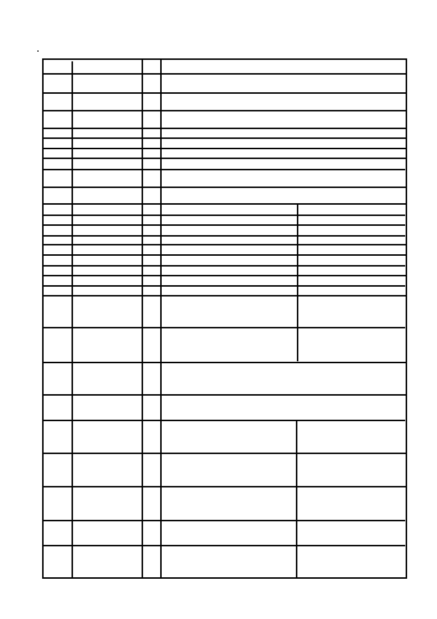
Pin No
Signal Name
Type
Description ARM System Mode
Description Standard Interface
Mode
2
POWER_GOOD
I
Power Monitor input. High for normal operation. Low forces the GP2021 into
Power Down mode.
3
NRESET_OP O
System Reset output (Active Low). Lasts for 4 MICRO_CLK cycles after all reset
conditions have cleared.
4
NARMSYS
I
Processor Mode Selection input. When Low, this input selects ARM System
mode. When High, Standard Interface mode is selected.
5
XIN
I
Crystal input connection to Real Time Clock.
6
XOUT
O
Crystal output connection from Real Time Clock.
7
TXA
O
Transmit Data output from Channel A of the Dual UART.
8
TXB
O
Transmit Data output from Channel B of the Dual UART.
9
RXA
1
Receive Data input to Channel A of the Dual UART. This pin acts as a master clock
input in Digital System Test mode.
10
RXB
I
Receive Data input to Channel B of the Dual UART. This pin acts as the Real Time
Clock reset in Digital System Test mode.
11
NROM / NC
O
ROM Chip Select output (Active Low).
Unused output. (Do not connect.)
12
NEEPROM / NC
O
EEPROM Chip Select output (Active Low)
Unused output. (Do not connect.)
13
NSPARE_CS / NC
O
Spare Chip Select output (Active Low).
Unused output. (Do not connect.)
16
NRAM / NC
O
RAM Chip Select output (Active Low).
Unused output. (Do not connect.)
17
NW0 / NC
O
Byte 0 Write Strobe output (Active Low).
Unused output. (Do not connect.)
18
NW1 / NC
O
Byte 1 Write Strobe output (Active Low).
Unused output. (Do not connect.)
19
NW2 / NC
O
Byte 2 Write Strobe output (Active Low).
Unused output. (Do not connect.)
20
NW3 / NC
O
Byte 3 Write Strobe output (Active Low).
Unused output. (Do not connect.)
21
NRD / NC
O
Read Data Strobe output (Active Low).
Unused output. (Do not connect.)
22
ARM_ALE / NC
O
ALE output to the microprocessor
Unused output. (Do not connect.)
(Active High). Controls the transparent
latches at the microprocessor address
outputs.
23
DBE / NC
O
Data Bus Enable output to the
Unused output. (Do not connect.)
microprocessor. When Low, places the
microprocessor data bus drivers in a
high impedance state.
24
ACCUM_INT
O
A free running interrupt to the microprocessor. It allows control of data transfer
between the accumulators in the correlator and the microprocessor. It is active
Low when configured for ARM System mode or Motorola mode and is active High
in Intel mode.
25
MEAS_INT
O
An interrupt to the microprocessor. It allows control of measurement data transfer
between the correlator and the microprocessor. It is active Low when configured
for ARM System mode or Motorola mode and is active High in Intel mode.
26
NBW / WRPROG
I
Byte/Word input from the
Write–Read Program input. In Intel
microprocessor. Low indicates a byte
mode, High selects 486 style
transfer, and High a word transfer.
interface and Low 186 style.
Unused in Motorola mode
27
NMREQ / DISCIP2
I
Memory Request input from the
Multi–purpose discrete input.
microprocessor. Low indicates that the
microprocessor requires a memory
access during the following cycle.
28
NOPC / NINTELMOT
I
Opcode fetch input from the
High selects Motorola mode and
microprocessor. Low indicates that an
Low Intel mode.
instruction is being fetched and High
that data is being transferred.
29
NRW / DISCIP3
I
Read/Write Select input from the
Multi–purpose discrete input.
microprocessor. Low indicates a read
cycle and High a write cycle.
30
MCLK / NC
O
Microprocessor Clock output
Unused output. (Do not connect.)
(nominally 20MHz). Its phases can be
stretched under control of the
Microprocessor Interface.
相关PDF资料 |
PDF描述 |
|---|---|
| GRM40Y5V105Z16 | Circular Connector; MIL SPEC:MIL-C-26482, Series I, Solder; Body Material:Aluminum; Series:PT06; No. of Contacts:21; Connector Shell Size:22; Connecting Termination:Solder; Circular Shell Style:Straight Plug; Body Style:Straight |
| GRM42-6X5R475K10 | 50/100M SOT-23 CMOS RF LDO REGULATORS |
| GT- 32090 | Highly Integrated Single-Chip System Controller(高集成单片系统控制器) |
| GT-48001A | Switched Ethernet Controller For 10BaseX(10BaseX交换式快速以太网控制器) |
| GT-48002A | Switched Fast Ethernet Controller for 100BaseX(100BaseX交换式快速以太网控制器) |
相关代理商/技术参数 |
参数描述 |
|---|---|
| GP2021IGGQ1R | 制造商:未知厂家 制造商全称:未知厂家 功能描述:Correlator |
| GP202K | 制造商:GTM 制造商全称:GTM 功能描述:SURFACE MOUNT,SWITCHING DIODE |
| GP2030S | 制造商:GTM 制造商全称:GTM 功能描述:N AND P-CHANNEL ENHANCEMENT MODE POWER MOSFET |
| GP2-031X250-50 | 制造商:GROOV-PIN 功能描述: |
| GP204 | 制造商:DEC 制造商全称:DEC 功能描述:2 AMP SOFT GLASS PASSIVATED DIODES |
发布紧急采购,3分钟左右您将得到回复。