- 您现在的位置:买卖IC网 > PDF目录67672 > GP2021 (Mitel Networks Corporation) GPS 12 channel Correlator Advance Information PDF资料下载
参数资料
| 型号: | GP2021 |
| 厂商: | Mitel Networks Corporation |
| 英文描述: | GPS 12 channel Correlator Advance Information |
| 中文描述: | 全球定位系统12通道相关器研究进展信息 |
| 文件页数: | 5/62页 |
| 文件大小: | 372K |
| 代理商: | GP2021 |
第1页第2页第3页第4页当前第5页第6页第7页第8页第9页第10页第11页第12页第13页第14页第15页第16页第17页第18页第19页第20页第21页第22页第23页第24页第25页第26页第27页第28页第29页第30页第31页第32页第33页第34页第35页第36页第37页第38页第39页第40页第41页第42页第43页第44页第45页第46页第47页第48页第49页第50页第51页第52页第53页第54页第55页第56页第57页第58页第59页第60页第61页第62页
13
GP2021
Pin Name
Logic Level
NW<3:0> / NC
Low
NRD / NC
Low
NRAM
Low
(standard interface mode)
NRAM
NB RAM
(ARM system mode)
NROM / NC
High Impedance
NSPARE_CS/NC
High Impedance
NEEPROM / NC
High Impedance
TXA,TXB
Low
ACCUM_INT
High Impedance
Pin Name
Logic Level
MEAS_INT
High Impedance
A
BORT / MICRO_CLK
Low
MCLK / NC
Low
ARM_ALE / NC
Low
DBE / NC
Low
NRESET_OP
Low
DISCOP
High Impedance
SAMPCLK
Low
XOUT
Active
Table 4 : Output Logic Levels in Power Down Mode
Hardware Reset Generation
The manner in which a hardware reset occurs depends on
whether the GP2021 is in ARM System mode or Standard
Interface mode. During a hardware reset, the NRESET_OP
pin is taken Low and the reset signal is applied within the
GP2021 to all blocks except the Real Time Clock.
There are 3 sources of hardware resets common to both
ARM System and Standard Interface modes, with an
additional
source
in
Standard
Interface
mode:
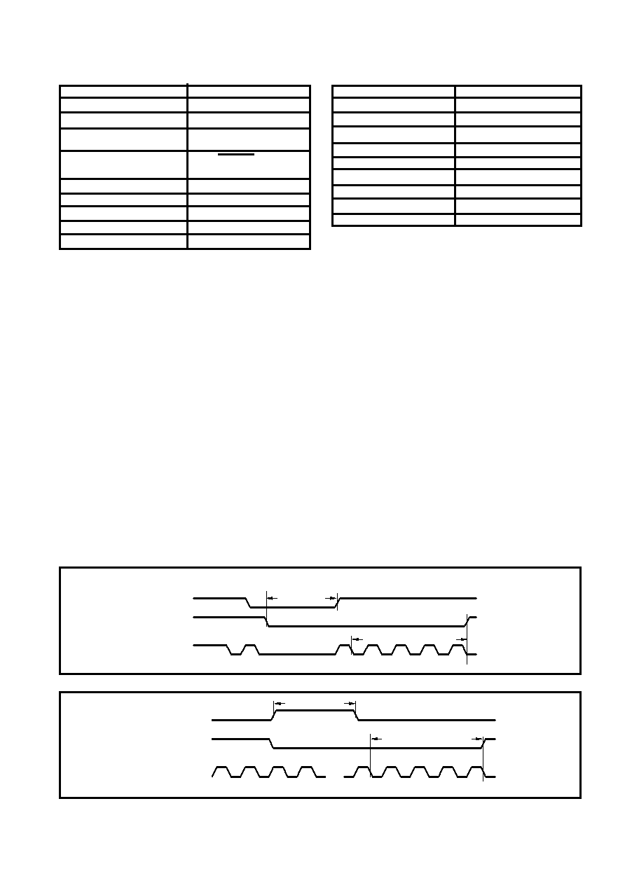
POWER_GOOD: A hardware reset will occur if this pin is
taken Low, as shown in Fig. 9. The purpose of this input is to
detect a power failure. If the NBRAM pin is held Low in ARM
System mode, the internal Power Down mode is not entered
until about 6ns after the falling edge of MICRO_CLK,
otherwise it is entered immediately. This allows for RAM write
cycles to complete sensibly when Battery Backed–Up RAM is
used,
with
no
corruption
of
RAM
data.
Watchdog: An expiry of the watchdog will result in a
hardware reset as shown in Fig. 10. This reset will clear the
watchdog whose time–out period is 2–3 seconds.
PLL_LOCK: The PLL_LOCK pin is used to indicate (when
High),that the phase locked loop in the RF front end, which
generates the master clock, is in lock. This signal is filtered
within the GP2021 and the reset state associated with it is only
de–activated if the PLL_LOCK input has been high for
approximately 50 ms as shown in Fig. 11.
NRESET_IP: In addition to the 3 reset sources described
above, an active Low NRESET_IP pin is available in Standard
Interface mode if the system resets are to be generated
externally. Fig. 12 shows a NRESET_IP generated reset.
Note that the NRESET_OP pin will go High 4 MICRO_CLK
cycles after all hardware reset sources have cleared. This
fulfills the reset requirements of the ARM60 microprocessor.
For information on the state of the registers following a
hardware reset refer to the Detailed Description of Registers
section.
System Error Status Register
This allows the software to determine whether the source
of a hardware reset was from a power failure, a PLL_LOCK
failure, watchdog timeout or from an external reset in Standard
Interface mode. For further information refer to the Detailed
Description of Registers section.
MICRO_CLK/
NRESET_OP
POWER_GOOD
4 CYCLES
MCLK
Power Down Mode
Fig. 9 : POWER_GOOD Hardware Reset Generation (NARMSYS = ‘0’, NBRAM =‘0’)
MICRO_CLK/
NRESET_OP
WATCHDOG
122 s
4 CYCLES
MCLK
Fig. 10 : Watchdog Hardware Reset Genera-
相关PDF资料 |
PDF描述 |
|---|---|
| GRM40Y5V105Z16 | Circular Connector; MIL SPEC:MIL-C-26482, Series I, Solder; Body Material:Aluminum; Series:PT06; No. of Contacts:21; Connector Shell Size:22; Connecting Termination:Solder; Circular Shell Style:Straight Plug; Body Style:Straight |
| GRM42-6X5R475K10 | 50/100M SOT-23 CMOS RF LDO REGULATORS |
| GT- 32090 | Highly Integrated Single-Chip System Controller(高集成单片系统控制器) |
| GT-48001A | Switched Ethernet Controller For 10BaseX(10BaseX交换式快速以太网控制器) |
| GT-48002A | Switched Fast Ethernet Controller for 100BaseX(100BaseX交换式快速以太网控制器) |
相关代理商/技术参数 |
参数描述 |
|---|---|
| GP2021IGGQ1R | 制造商:未知厂家 制造商全称:未知厂家 功能描述:Correlator |
| GP202K | 制造商:GTM 制造商全称:GTM 功能描述:SURFACE MOUNT,SWITCHING DIODE |
| GP2030S | 制造商:GTM 制造商全称:GTM 功能描述:N AND P-CHANNEL ENHANCEMENT MODE POWER MOSFET |
| GP2-031X250-50 | 制造商:GROOV-PIN 功能描述: |
| GP204 | 制造商:DEC 制造商全称:DEC 功能描述:2 AMP SOFT GLASS PASSIVATED DIODES |
发布紧急采购,3分钟左右您将得到回复。