参数资料
| 型号: | HI7188IN |
| 厂商: | Intersil |
| 文件页数: | 8/24页 |
| 文件大小: | 0K |
| 描述: | CONV A/D 16BIT 8:1 MUX 44-MQFP |
| 标准包装: | 96 |
| 位数: | 16 |
| 采样率(每秒): | 240 |
| 数据接口: | QSPI?,串行,SPI? |
| 转换器数目: | 1 |
| 功率耗散(最大): | 50mW |
| 电压电源: | 模拟和数字,双 ± |
| 工作温度: | -40°C ~ 85°C |
| 安装类型: | 表面贴装 |
| 封装/外壳: | 44-QFP |
| 供应商设备封装: | 44-MQFP(10x10) |
| 包装: | 管件 |
| 输入数目和类型: | 8 个差分,单极;8 个差分,双极 |
16
System Negative Full Scale Calibration
The system negative full scale calibration mode is a process
that allows the user to lump negative gain errors of external
circuitry and the internal gain errors of the HI7188 together to
calculate the negative transfer function of the system. This
mode will convert the external differential signal applied to the
VIN inputs and then store that value in the system negative full
scale calibration RAM for that physical channel. To invoke the
system negative full scale calibration the user applies the
“negative full scale voltage”, which must be equal to Vref, to the
physical channel requiring calibration, then writes the related
CCR byte indicating negative full scale calibration is required
(see note below). The next time this logical channel is
converted, the microsequencer performs calibration and
updates the related system negative full scale calibration RAM.
Next the internal microsequencer places that logical channel
back into the conversion mode and updates the CCR byte.
TEMPORARY NOTE: In bipolar mode, the user MUST perform
negative full scale calibration with the exact differential voltage
applied to the Vref pins, otherwise large errors will occur at the zero
crossing point. During normal conversions, the error occurs when the
input is at the offset calibration point. At this point, plus or minus 1/2
LSB, the output code will be either the true half scale reading of
7FFF/8000 (offset binary coding) or negative full scale 0000.
Offset and Gain Adjust Limits
Whenever a calibration mode is used, there are limits to the
amount of offset and gain which can be adjusted. For both
bipolar and unipolar modes the minimum and maximum
input spans are 0.2 x VREF/GAIN and 1.2 x VREF/GAIN
respectively. In the unipolar mode the offset plus the span
cannot exceed the 1.2 x VREF/GAIN limit. So, if the span is
at its minimum value of 0.2 x VREF/GAIN, the offset must be
less than 1 x VREF/GAIN. In bipolar mode the span is
equidistant around the voltage used for the zero scale point.
For this mode the offset plus half the span cannot exceed
1.2 x VREF/GAIN. If the span is at ±0.2 x VREF/GAIN, then
the offset can not be greater than
±2 x VREF/GAIN.
Range Detection
In addition to the calibration process, the converter detects over
range above positive full scale and under range below minus
full scale conditions. Over or under range detection affects the
output data coding as described in the Data Coding section.
Over range detection is identical for both bipolar and
unipolar operation. Over range is detected by comparing the
offset corrected lter output to the positive gain coefcient. If
the current offset corrected lter value is greater than the
positive gain coefcient, an over range condition is detected.
In unipolar mode, under range is detected by sampling the
sign bit of the offset calibrated data. If the sign bit is logic 1,
signifying a negative voltage, an under range condition exists.
In bipolar mode, under range is detected by comparing the
offset corrected lter output to the negative gain coefcient.
If the current offset corrected lter value is less than the
negative gain coefcient, an under range condition is
detected.
Data Coding
The calibrated data can be obtained in one of various numerical
codes depending on the bipolar/unipolar mode bit and the two’s
complement coding bit. In bipolar mode, if the two’s
complement bit is high, the output is two’s complement. In
bipolar mode, offset binary coding is used when the two’s
complement coding bit is low. In unipolar mode, only binary
coding is available and the two’s complement coding bit is a
don’t care.
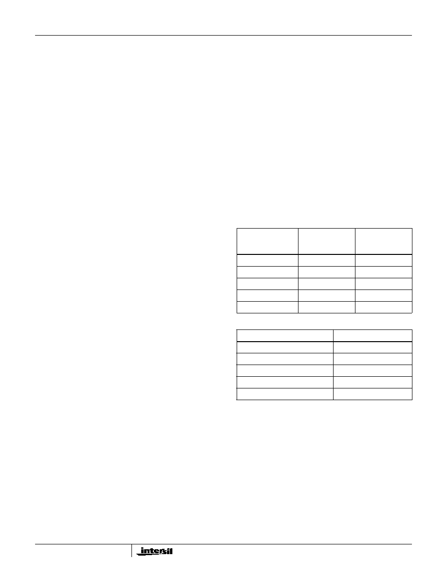
The output coding for the HI7188 is shown in Tables 4 and 5.
VZS represents the applied zero scale input during system
offset calibration. VPFS represents the applied positive full
scale input during system positive full scale calibration.
VNFS represents the applied negative full scale input during
system negative full scale calibration.
When the range detection logic determines an over range,
the converter output will clamp at the >(VPFS - 1.5 LSB)
output as described in Tables 4 and 5. When the range
detection logic determines an under range, the converter
output will clamp at the <(VNFS + 0.5 LSB) output
described in Table 4 or the <(VZS + 0.5 LSB) output
described in Table 5.
Data RAM
The Data RAM block is comprised of two 8 x 16 memory
elements which store conversion results after calibration and
data coding. Two RAMs are required to allow a one channel
scan buffer per logical channel. The user can only READ from
the data RAM. For illustration, these elements are labeled
TABLE 4. BIPOLAR MODE OUTPUT CODES (HEX)
INPUT VOLTAGE
TWO’S
COMPLEMENT
CODE
OFFSET
BINARY CODE
>(VPFS - 1.5 LSB)
7FFF
FFFF
VPFS - 1.5 LSB
7FFF/7FFE
FFFF/FFFE
VZS - 0.5 LSB
0000/FFFF
8000/7FFF
VNFS + 0.5 LSB
8001/8000
0001/0000
<(VNFS + 0.5 LSB)
8000
0000
TABLE 5. UNIPOLAR MODE DATA OUTPUT CODES (HEX)
INPUT VOLTAGE
BINARY CODE
>(VPFS - 1.5 LSB)
FFFF
VPFS - 1.5 LSB
FFFF/FFFE
VPFS/2 - 0.5 LSB
8000/7FFF
VZS + .5 LSB
0001/0000
<(VZS + 0.5 LSB)
0000
HI7188
相关PDF资料 |
PDF描述 |
|---|---|
| HI7190IP | IC ADC 24BIT PROGBL SER 20-PDIP |
| HI7191IP | IC ADC 24BIT PROGBL SER 20-PDIP |
| HI9P5701K-5 | CONV A/D 6BIT 30MSPS 18-SOIC |
| HMC700LP4E | IC FRACT-N PLL 16BIT 24QFN |
| HMC703LP4E | IC FRACT-N PLL W/SWEEPR 24QFN |
相关代理商/技术参数 |
参数描述 |
|---|---|
| HI7188IP | 制造商:Rochester Electronics LLC 功能描述:- Bulk 制造商:Analog Devices 功能描述:IC 16BIT ADC 7188 DIP40 制造商:Harris Corporation 功能描述: |
| HI7190 | 制造商:INTERSIL 制造商全称:Intersil Corporation 功能描述:null24-Bit, High Precision, Sigma Delta A/D Converter |
| HI7190 WAF | 制造商:Harris Corporation 功能描述: |
| HI7190_06 | 制造商:INTERSIL 制造商全称:Intersil Corporation 功能描述:24-Bit, High Precision, Sigma Delta A/D Converter |
| HI7190EVAL | 功能描述:EVALUATION PLATFORM HI7190 RoHS:否 类别:编程器,开发系统 >> 评估板 - 模数转换器 (ADC) 系列:- 产品培训模块:Obsolescence Mitigation Program 标准包装:1 系列:- ADC 的数量:1 位数:12 采样率(每秒):94.4k 数据接口:USB 输入范围:±VREF/2 在以下条件下的电源(标准):- 工作温度:-40°C ~ 85°C 已用 IC / 零件:MAX11645 已供物品:板,软件 |
发布紧急采购,3分钟左右您将得到回复。