- 您现在的位置:买卖IC网 > PDF目录16296 > LTC4110EUHF#PBF (Linear Technology)IC BATTERY BACKUP MANAGER 38-QFN PDF资料下载
参数资料
| 型号: | LTC4110EUHF#PBF |
| 厂商: | Linear Technology |
| 文件页数: | 41/52页 |
| 文件大小: | 0K |
| 描述: | IC BATTERY BACKUP MANAGER 38-QFN |
| 标准包装: | 52 |
| 功能: | 备份管理 |
| 电池化学: | 铅酸,锂离子,锂聚合物,镍镉,镍氢,超级电容器 |
| 电源电压: | 4.5 V ~ 19 V |
| 工作温度: | -40°C ~ 85°C |
| 安装类型: | 表面贴装 |
| 封装/外壳: | 38-WFQFN 裸露焊盘 |
| 供应商设备封装: | 38-QFN(5x7) |
| 包装: | 管件 |
| 产品目录页面: | 1341 (CN2011-ZH PDF) |
第1页第2页第3页第4页第5页第6页第7页第8页第9页第10页第11页第12页第13页第14页第15页第16页第17页第18页第19页第20页第21页第22页第23页第24页第25页第26页第27页第28页第29页第30页第31页第32页第33页第34页第35页第36页第37页第38页第39页第40页当前第41页第42页第43页第44页第45页第46页第47页第48页第49页第50页第51页第52页
�� �
�
�LTC4110�
�APPLICATIONS� INFORMATION�
�Avoid� capacitors� with� high� leakage� currents.� See� the�
�Programming� Charge� Time� with� TIMER� and� V� REF� Pins�
�section� for� details� concerning� the� V� REF� pin.� For� minimum�
�delay� open� the� ACPDLY� pin.�
�BAT� PIN� CURRENT� IN� IDLE� MODE�
�When� LTC4110� is� in� IDLE� mode� (i.e.,� not� in� charge,� calibra-�
�tion� or� backup� mode),� there� will� be� a� typical� 30μA� current�
�pulled� from� the� battery� through� the� BAT� pin,� if� this� current�
�is� of� concern,� a� diode� in� series� with� a� resistor� can� be� con-�
�nected� between� DCIN� and� battery� to� compensate� it.�
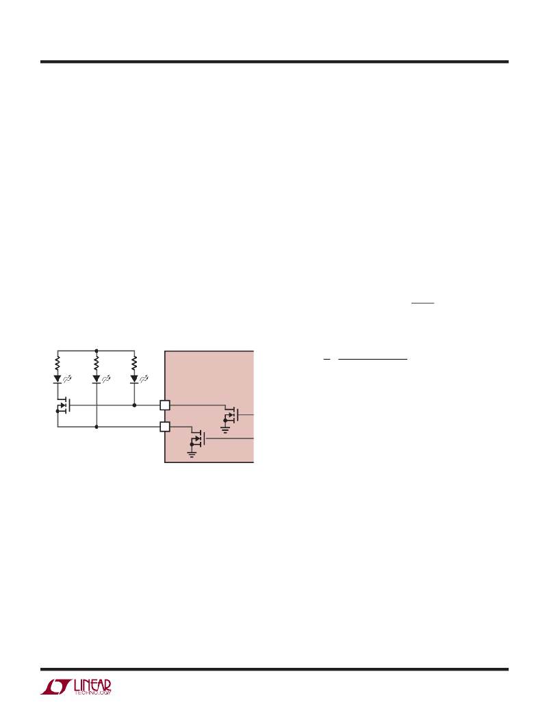
�SHOW� BATTERY� FULL� WITH� ACPB� AND� CHGB�
�Tie� the� source� of� an� N-MOSFET� to� ACPb,� gate� to� CHGb� and�
�This� current� ramp� starts� at� zero� right� after� the� primary� side�
�MOSFET� (CHGFET� in� charge� mode,� DCHFET� in� calibration�
�mode)� is� turned� on.� The� current� rises� linearly� towards� a�
�peak� of� V� SEC� /400k� (where� V� SEC� =� BAT� in� charge� mode,�
�V� SEC� =� DCIN� in� calibration� mode),� shutting� off� once� the�
�primary� side� MOSFET� is� turned� off.� A� series� resistor� (R� SL� )�
�connecting� the� I� SENSE� pin� to� the� current� sense� resistor�
�(R� SNS(FET)� )� thus� develops� a� ramping� voltage� drop.� From�
�the� perspective� of� the� I� SENSE� pin,� this� ramping� voltage�
�adds� to� the� voltage� across� the� sense� resistor,� effectively�
�reducing� the� current� comparator� threshold� in� proportion�
�to� duty� cycle.� This� stabilizes� the� control� loop� against�
�subharmonic� oscillation.� The� amount� of� reduction� in� the�
�current� comparator� threshold� (� Δ� V� ISENSE� )� can� be� calculated�
�using� the� following� equation:�
�drain� in� series� with� R� to� an� LED� to� show� battery� full.� In�
�that� case� if� CHG� or� ACP� status� LED� is� not� needed,� replace�
�it� with� a� short� but� keep� the� pull-up� resistor.�
�Δ� V� ISENSE� =� DUTY� CYCLE� ?�
�V� SEC�
�400k�
�?� R� SL�
�To� program� m� =� m2,�
�1� 400� k� ?� R� SNS� ,� FET�
�+5V�
�R� SL� =�
�N� F� ?� Lm�
�?�
�FULL�
�ACP�
�CHG�
�CHGb�
�ACPb�
�where�
�N� =� transformer� turns� ratio� N� BAT� /N� DCIN�
�R� SNS(FET)� =� sense� resistor� connected� between� MOSFET�
�and� GND�
�f� =� switching� frequency�
�4110� F18�
�Figure� 18.� Display� Battery� Full�
�FLYBACK� COMPENSATION�
�The� values� given� for� the� I� TH� pin� in� the� application� schematics�
�have� been� found� to� compensate� both� the� voltage� loop� and�
�current� loop� quite� well.� However,� if� the� resistor� connected�
�to� I� CHG� ,� I� CAL� or� I� PCC� is� larger� than� 100k,� a� 37k� resistor� in�
�series� with� a� 100nF� capacitor� should� also� be� connected�
�between� that� pin� and� GND� to� compensate� the� loop.�
�SLOPE� COMPENSATION�
�The� LTC4110� injects� a� ramping� current� through� its� I� SENSE�
�pin� into� an� external� slope� compensation� resistor� (R� SL� ).�
�Lm� =� magnetizing� inductance� of� the� transformer�
�Designs� not� needing� slope� compensation� may� replace�
�R� SL� with� a� short.�
�CALCULATING� IC� POWER� DISSIPATION�
�The� power� dissipation� of� the� LTC4110� is� dependent� upon�
�the� gate� charge� of� the� two� MOSFETs� (Q� G1� and� Q� G2� ).� The�
�gate� charge� is� determined� from� the� manufacturer’s� data�
�sheet� and� is� dependent� upon� both� the� gate� voltage� swing�
�and� the� drain� voltage� swing� of� the� MOSFET.� Use� 5V� for�
�the� gate� voltage� swing� and� V� DCIN� for� the� drain� voltage�
�swing.�
�P� D� =� V� DCIN� ?� (f� OSC� (Q� G1� +� Q� G2� )� +� I� Q� )�
�4110fb�
�41�
�相关PDF资料 |
PDF描述 |
|---|---|
| 3-6754412-6 | CA,XG,MTRJ-SC |
| ECO-S2DB102EA | CAP ALUM 1000UF 200V 20% SNAP |
| 3-6754411-6 | CA,XG,MTRJ-SC |
| RCM10DRYI-S13 | CONN EDGECARD 20POS .156 EXTEND |
| ECO-S2WB181DA | CAP ALUM 180UF 450V 20% SNAP |
相关代理商/技术参数 |
参数描述 |
|---|---|
| LTC4110EUHF-TR | 制造商:LINER 制造商全称:Linear Technology 功能描述:Battery Backup System Manager |
| LTC4110EUHF-TRPBF | 制造商:LINER 制造商全称:Linear Technology 功能描述:Battery Backup System Manager |
| LTC4120IUD#PBF | 制造商:Linear Technology 功能描述:BATTERY CHARGER, 400MA, QFN-16, Battery Type:Li-Ion, Li-Polymer, Input Voltage:4 |
| LTC4150 | 制造商:LINER 制造商全称:Linear Technology 功能描述:High Voltage, High-Side Current Sense |
| LTC4150_1 | 制造商:LINER 制造商全称:Linear Technology 功能描述:Coulomb Counter/ Battery Gas Gauge |
发布紧急采购,3分钟左右您将得到回复。