- 您现在的位置:买卖IC网 > Datasheet目录470 > MAX11008EVC16 (Maxim Integrated)EVAL KIT MAX11008 Datasheet资料下载
参数资料
| 型号: | MAX11008EVC16 |
| 厂商: | Maxim Integrated |
| 文件页数: | 20/67页 |
| 文件大小: | 0K |
| 描述: | EVAL KIT MAX11008 |
| 标准包装: | 1 |
| 系列: | * |
第1页第2页第3页第4页第5页第6页第7页第8页第9页第10页第11页第12页第13页第14页第15页第16页第17页第18页第19页当前第20页第21页第22页第23页第24页第25页第26页第27页第28页第29页第30页第31页第32页第33页第34页第35页第36页第37页第38页第39页第40页第41页第42页第43页第44页第45页第46页第47页第48页第49页第50页第51页第52页第53页第54页第55页第56页第57页第58页第59页第60页第61页第62页第63页第64页第65页第66页第67页
�� �
�
�Dual� RF� LDMOS� Bias� Controller� with�
�Nonvolatile� Memory�
�A� master� device� communicates� to� the� MAX11008� by�
�transmitting� the� proper� slave� address� followed� by� a�
�command� and/or� data� words.� Each� transmit� sequence�
�is� framed� by� a� START� (S)� or� repeated� START� (Sr)� con-�
�dition� and� a� STOP� (P)� condition.� Each� word� transmitted�
�over� the� bus� is� 8� bits� long� and� is� always� followed� by� an�
�acknowledge� clock� pulse.�
�The� MAX11008� SDA� and� SCL� drivers� are� open-drain�
�outputs,� requiring� a� pullup� resistor� (750� ?� or� greater)� to�
�generate� a� logic-high� voltage� (see� the� Typical�
�Application� Circuits).� Series� resistors� are� optional� for�
�noise� filtering.� These� series� resistors� protect� the� input�
�stages� of� the� MAX11008� from� high-voltage� spikes� on�
�the� bus� line,� and� minimize� crosstalk� and� undershoot� of�
�the� bus� signals.�
�Bit� Transfer�
�One� data� bit� is� transferred� during� each� SCL� clock�
�cycle.� The� data� on� SDA� must� remain� stable� during� the�
�high� period� of� the� SCL� clock� pulse.� Changes� in� SDA�
�while� SCL� is� high� are� control� signals� (see� the� START�
�and� STOP� Conditions� section).� Both� SDA� and� SCL� idle�
�high� when� the� I� 2� C� bus� is� not� busy.�
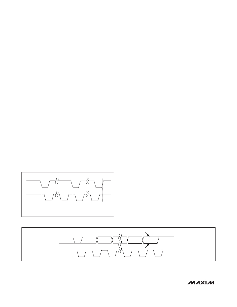
�START� and� STOP� Conditions�
�The� master� initiates� a� transmission� with� a� START� condi-�
�tion� (S),� which� is� a� high-to-low� transition� on� SDA� while�
�SCL� is� high.� The� master� terminates� a� transmission� with�
�a� STOP� condition� (P),� which� is� a� low-to-high� transition�
�on� SDA� while� SCL� is� high� (see� Figure� 5).� A� repeated�
�START� condition� (Sr)� can� be� used� in� place� of� a� STOP�
�condition� to� leave� the� bus� active� and� the� mode�
�unchanged� (see� the� HS� I� 2� C� Mode� section).�
�Acknowledge� Bits� and� Not-Acknowledge� Conditions�
�Data� transfers� are� framed� with� an� acknowledge� bit�
�(ACK)� or� a� not-acknowledge� bit� (NACK).� Both� the� mas-�
�ter� and� the� MAX11008� (slave)� generate� acknowledge�
�bits.� To� generate� an� acknowledge,� the� receiving� device�
�must� pull� SDA� low� before� the� rising� edge� of� the�
�acknowledge-related� clock� pulse� (ninth� clock� pulse)�
�and� keep� it� low� during� the� high� period� of� the� clock�
�pulse� (see� Figure� 6).�
�To� generate� a� not-acknowledge� condition,� the� receiver�
�allows� SDA� to� be� pulled� high� before� the� rising� edge� of�
�the� acknowledge-related� clock� pulse,� and� leaves� SDA�
�high� during� the� high� period� of� the� clock� pulse.�
�Monitoring� the� acknowledge� bits� allows� for� detection� of�
�unsuccessful� data� transfers.� An� unsuccessful� data�
�transfer� happens� if� a� receiving� device� is� busy� or� if� a�
�system� fault� has� occurred.� In� the� event� of� an� unsuc-�
�cessful� data� transfer,� the� bus� master� reattempts� com-�
�munication� at� a� later� time.�
�S�
�Sr�
�P�
�SDA�
�SCL�
�S� =� START.�
�Sr� =� REPEATED� START.�
�P� =� STOP.�
�Figure� 5.� START� and� STOP� Conditions�
�S�
�NOT� ACKNOWLEDGE�
�SDA�
�ACKNOWLEDGE�
�SCL�
�1�
�2�
�8�
�9�
�Figure� 6.� Acknowledge� Bits�
�20�
�______________________________________________________________________________________�
�相关PDF资料 |
PDF描述 |
|---|---|
| MAX11014BGTM+T | IC RF MESFET AMP 48-TQFN-EP |
| MAX12000ETB+T | IC AMP GPS FRONT 1575MHZ 10TDFN |
| MAX12005ETM+T | IC SATELLITE IF SWITCH 48-TQFN |
| MAX1385BUTM+ | IC RF LDMOS BIAS CNTRLR 48-TQFN |
| MAX1470EUI+T | IC RECEIVER 315MHZ 28-TSSOP |
相关代理商/技术参数 |
参数描述 |
|---|---|
| MAX11008EVKIT+ | 功能描述:放大器 IC 开发工具 MAX11008 Eval Kit RoHS:否 制造商:International Rectifier 产品:Demonstration Boards 类型:Power Amplifiers 工具用于评估:IR4302 工作电源电压:13 V to 23 V |
| MAX1100CWG | 制造商:Rochester Electronics LLC 功能描述: 制造商:Maxim Integrated Products 功能描述: |
| MAX1101 | 制造商:MAXIM 制造商全称:Maxim Integrated Products 功能描述:Single-Chip, 8-Bit CCD Digitizer with Clamp and 6-Bit PGA |
| MAX11014 | 制造商:MAXIM 制造商全称:Maxim Integrated Products 功能描述:Automatic RF MESFET Amplifier Drain-Current Controllers |
| MAX11014_08 | 制造商:MAXIM 制造商全称:Maxim Integrated Products 功能描述:Automatic RF MESFET Amplifier Drain-Current Controllers |
发布紧急采购,3分钟左右您将得到回复。