- 您现在的位置:买卖IC网 > PDF目录98009 > MAX14830ETM+ (MAXIM INTEGRATED PRODUCTS INC) SERIAL COMM CONTROLLER, QCC48 PDF资料下载
参数资料
| 型号: | MAX14830ETM+ |
| 厂商: | MAXIM INTEGRATED PRODUCTS INC |
| 元件分类: | 微控制器/微处理器 |
| 英文描述: | SERIAL COMM CONTROLLER, QCC48 |
| 封装: | 7 X 7 MM, ROHS COMPLIANT, TQFN-48 |
| 文件页数: | 67/68页 |
| 文件大小: | 2356K |
| 代理商: | MAX14830ETM+ |
第1页第2页第3页第4页第5页第6页第7页第8页第9页第10页第11页第12页第13页第14页第15页第16页第17页第18页第19页第20页第21页第22页第23页第24页第25页第26页第27页第28页第29页第30页第31页第32页第33页第34页第35页第36页第37页第38页第39页第40页第41页第42页第43页第44页第45页第46页第47页第48页第49页第50页第51页第52页第53页第54页第55页第56页第57页第58页第59页第60页第61页第62页第63页第64页第65页第66页当前第67页第68页
MAX14830
Quad Serial UART with 128-Word FIFOs
and Internal Oscillator
8
Stresses beyond those listed under “Absolute Maximum Ratings” may cause permanent damage to the device. These are stress ratings only, and functional
operation of the device at these or any other conditions beyond those indicated in the operational sections of the specifications is not implied. Exposure to absolute
maximum rating conditions for extended periods may affect device reliability.
(Voltages referenced to AGND.)
VL, VA, VEXT, XIN ................................................ -0.3V to +4.0V
V18, XOUT .................................................. -0.3V to (VA + 0.3V)
RST, IRQ, MOSI/A1, CS/A0, SCLK/SCL,
MISO/SDA, LDOEN, SPI/
I2C.................. -0.3V to (VL + 0.3V)
TX0, RX0, CTS0, GPIO0, GPIO1,
GPIO2, GPIO3..................................... -0.3V to (VEXT + 0.3V)
TX1, RX1, CTS1, GPIO4, GPIO5,
GPIO6, GPIO7..................................... -0.3V to (VEXT + 0.3V)
TX2, RX2, CTS2, GPIO8, GPIO9,
GPIO10, GPIO11................................. -0.3V to (VEXT + 0.3V)
TX3, RX3, CTS3, GPIO12, GPIO13,
GPIO14, GPIO15................................. -0.3V to (VEXT + 0.3V)
DGND.................................................................. -0.3V to +0.3V
Continuous Power Dissipation (TA = +70NC)
48-Pin TQFN (derate 38.5mW/NC above +70NC).....3076.9mW
Operating Temperature Range ........................ -40NC to +85NC
Maximum Junction Temperature ................................. +150NC
Storage Temperature Range ......................... -65NC to +150NC
Lead Temperature (soldering, 10s) ..................................300NC
Soldering Temperature (reflow) .....................................+260NC
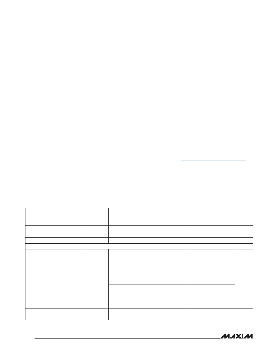
DC ELECTRICAL CHARACTERISTICS
(VA = +2.35V to +3.6V, VL = +1.71V to +3.6V, VEXT = +1.71V to +3.6V, TA = -40NC to +85NC, unless otherwise noted. Typical values
are at VA = +2.5V, VL = +1.8V, VEXT = +2.8V, TA = +25NC.) (Notes 2, 3)
ABSOLUTE MAXIMUM RATINGS
Note 1: Package thermal resistances were obtained using the method described in JEDEC specification JESD51-7, using a four-
layer board. For detailed information on package thermal considerations, refer to www.maxim-ic.com/thermal-tutorial.
PACKAGE THERMAL CHARACTERISTICS (Note 1)
TQFN
Junction-to-Ambient Thermal Resistance (BJA)...........26NC/W
Junction-to-Case Thermal Resistance (BJC)..................1NC/W
PARAMETER
SYMBOL
CONDITIONS
MIN
TYP
MAX
UNITS
Digital Interface Supply Voltage
VL
1.71
3.6
V
Analog Supply Voltage
VA
2.35
3.6
V
UART Interface Logic Supply
Voltage
VEXT
1.71
3.6
V
Logic Supply Voltage
V18
1.65
1.95
V
CURRENT CONSUMPTION
VA Supply Current
IA
1.8MHz crystal oscillator active, PLL dis-
abled, SPI/I2C interface idle, UART inter-
faces idle, VLDOEN = VL
400
F
A
Baud rate = 1Mbps, 20MHz external clock,
SPI/I2C interface idle, PLL disabled, all
UARTs in loopback mode, VLDOEN = 0V
0.5
mA
Internal oscillator enabled, PLL = 6x, SPI/
I2C interface idle, baud rate = 115kbps, all
UARTs in loopback mode, VLDOEN = 0V
5
VA Shutdown Supply Current
IASHDN
Shutdown mode, VLDOEN = 0V, VRST = 0V,
all inputs and outputs are idle
35
F
A
相关PDF资料 |
PDF描述 |
|---|---|
| MAX3624AETJ+ | 312.5 MHz, OTHER CLOCK GENERATOR, QCC32 |
| MAX3638ETM+ | 800 MHz, OTHER CLOCK GENERATOR, QCC48 |
| MAX3679CTJ+ | 625 MHz, OTHER CLOCK GENERATOR, QCC32 |
| MAX7329AUP+ | 8 I/O, PIA-GENERAL PURPOSE, PDSO20 |
| MAX7329AAP+ | 8 I/O, PIA-GENERAL PURPOSE, PDSO20 |
相关代理商/技术参数 |
参数描述 |
|---|---|
| MAX14830ETM+ | 功能描述:UART 接口集成电路 Quad Serial UART w/128-Word FIFOs RoHS:否 制造商:Texas Instruments 通道数量:2 数据速率:3 Mbps 电源电压-最大:3.6 V 电源电压-最小:2.7 V 电源电流:20 mA 最大工作温度:+ 85 C 最小工作温度:- 40 C 封装 / 箱体:LQFP-48 封装:Reel |
| MAX14830ETM+T | 功能描述:UART 接口集成电路 Quad Serial UART w/128-Word FIFOs RoHS:否 制造商:Texas Instruments 通道数量:2 数据速率:3 Mbps 电源电压-最大:3.6 V 电源电压-最小:2.7 V 电源电流:20 mA 最大工作温度:+ 85 C 最小工作温度:- 40 C 封装 / 箱体:LQFP-48 封装:Reel |
| MAX14830EVKIT# | 功能描述:界面开发工具 MAX14830 Eval Kit RoHS:否 制造商:Bourns 产品:Evaluation Boards 类型:RS-485 工具用于评估:ADM3485E 接口类型:RS-485 工作电源电压:3.3 V |
| MAX14830EVKIT+ | 制造商:Maxim Integrated Products 功能描述:QUAD UART EV-KIT WITH IO-LINK AND MULTIPROTOCOL - Boxed Product (Development Kits) |
| MAX1483C/D+ | 功能描述:RS-485接口IC low-power transceivers for RS-485 and RS-422 communication RoHS:否 制造商:Texas Instruments 数据速率:250 Kbps 工作电源电压:3.3 V 电源电流:750 uA 工作温度范围:- 40 C to + 125 C 安装风格:SMD/SMT 封装 / 箱体:SOIC-8 封装:Tube |
发布紧急采购,3分钟左右您将得到回复。