- 您现在的位置:买卖IC网 > PDF目录3857 > PIC18F45J50-I/ML (Microchip Technology)IC PIC MCU FLASH 32K 2V 44-QFN PDF资料下载
参数资料
| 型号: | PIC18F45J50-I/ML |
| 厂商: | Microchip Technology |
| 文件页数: | 83/164页 |
| 文件大小: | 0K |
| 描述: | IC PIC MCU FLASH 32K 2V 44-QFN |
| 产品培训模块: | XLP Deep Sleep Mode PIC18 J Series MCU Overview 8-bit PIC® Microcontroller Portfolio |
| 标准包装: | 45 |
| 系列: | PIC® XLP™ 18F |
| 核心处理器: | PIC |
| 芯体尺寸: | 8-位 |
| 速度: | 48MHz |
| 连通性: | I²C,SPI,UART/USART,USB |
| 外围设备: | 欠压检测/复位,DMA,POR,PWM,WDT |
| 输入/输出数: | 34 |
| 程序存储器容量: | 32KB(16K x 16) |
| 程序存储器类型: | 闪存 |
| RAM 容量: | 3.8K x 8 |
| 电压 - 电源 (Vcc/Vdd): | 2.15 V ~ 3.6 V |
| 数据转换器: | A/D 13x10b |
| 振荡器型: | 内部 |
| 工作温度: | -40°C ~ 85°C |
| 封装/外壳: | 44-VQFN 裸露焊盘 |
| 包装: | 管件 |
| 产品目录页面: | 657 (CN2011-ZH PDF) |
| 配用: | AC164322-ND - MODULE SOCKET MPLAB PM3 28/44QFN |
第1页第2页第3页第4页第5页第6页第7页第8页第9页第10页第11页第12页第13页第14页第15页第16页第17页第18页第19页第20页第21页第22页第23页第24页第25页第26页第27页第28页第29页第30页第31页第32页第33页第34页第35页第36页第37页第38页第39页第40页第41页第42页第43页第44页第45页第46页第47页第48页第49页第50页第51页第52页第53页第54页第55页第56页第57页第58页第59页第60页第61页第62页第63页第64页第65页第66页第67页第68页第69页第70页第71页第72页第73页第74页第75页第76页第77页第78页第79页第80页第81页第82页当前第83页第84页第85页第86页第87页第88页第89页第90页第91页第92页第93页第94页第95页第96页第97页第98页第99页第100页第101页第102页第103页第104页第105页第106页第107页第108页第109页第110页第111页第112页第113页第114页第115页第116页第117页第118页第119页第120页第121页第122页第123页第124页第125页第126页第127页第128页第129页第130页第131页第132页第133页第134页第135页第136页第137页第138页第139页第140页第141页第142页第143页第144页第145页第146页第147页第148页第149页第150页第151页第152页第153页第154页第155页第156页第157页第158页第159页第160页第161页第162页第163页第164页
PIC18F46J50 FAMILY
DS39931D-page 30
2011 Microchip Technology Inc.
2.2
Power Supply Pins
2.2.1
DECOUPLING CAPACITORS
The use of decoupling capacitors on every pair of
power supply pins, such as VDD, VSS, AVDD and
AVSS, is required.
Consider the following criteria when using decoupling
capacitors:
Value and type of capacitor: A 0.1
F (100 nF),
10-20V capacitor is recommended. The capacitor
should be a low-ESR device, with a resonance
frequency in the range of 200 MHz and higher.
Ceramic capacitors are recommended.
Placement on the printed circuit board: The
decoupling capacitors should be placed as close
to the pins as possible. It is recommended to
place the capacitors on the same side of the
board as the device. If space is constricted, the
capacitor can be placed on another layer on the
PCB using a via; however, ensure that the trace
length from the pin to the capacitor is no greater
than 0.25 inch (6 mm).
Handling high-frequency noise: If the board is
experiencing high-frequency noise (upward of
tens of MHz), add a second ceramic type capaci-
tor in parallel to the above described decoupling
capacitor. The value of the second capacitor can
be in the range of 0.01
F to 0.001 F. Place this
second capacitor next to each primary decoupling
capacitor. In high-speed circuit designs, consider
implementing a decade pair of capacitances as
close to the power and ground pins as possible
(e.g., 0.1
F in parallel with 0.001 F).
Maximizing performance: On the board layout
from the power supply circuit, run the power and
return traces to the decoupling capacitors first,
and then to the device pins. This ensures that the
decoupling capacitors are first in the power chain.
Equally important is to keep the trace length
between the capacitor and the power pins to a
minimum, thereby reducing PCB trace
inductance.
2.2.2
BULK CAPACITORS
On boards with power traces running longer than
six inches in length, it is suggested to use a larger
energy storing capacitor for integrated circuits, includ-
ing microcontrollers, to supply a local power source.
The value of this capacitor should be determined based
on the trace resistance that connects the power supply
source to the device, and the maximum current drawn
by the device in the application. In other words, select
the capacitor so that it meets the acceptable voltage
sag at the device. Typical values range from 4.7
F to
47
F.
2.3
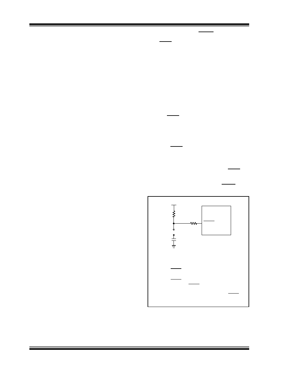
Master Clear (MCLR) Pin
The MCLR pin provides two specific device
functions: Device Reset, and Device Programming
and Debugging. If programming and debugging are
not required in the end application, a direct
connection to VDD may be all that is required. The
addition of other components, to help increase the
application’s resistance to spurious Resets from
voltage
sags,
may
be
beneficial.
A
typical
configuration is shown in Figure 2-1. Other circuit
designs may be implemented, depending on the
application’s requirements.
During programming and debugging, the resistance
and capacitance that can be added to the pin must
be considered. Device programmers and debuggers
drive the MCLR pin. Consequently, specific voltage
levels (VIH and VIL) and fast signal transitions must
not be adversely affected. Therefore, specific values
of R1 and C1 will need to be adjusted based on the
application and PCB requirements. For example, it is
recommended that the capacitor, C1, be isolated
from the MCLR pin during programming and
debugging operations by using a jumper (Figure 2-2).
The
jumper
is
replaced
for
normal
run-time
operations.
Any components associated with the MCLR pin
should be placed within 0.25 inch (6 mm) of the pin.
FIGURE 2-2:
EXAMPLE OF MCLR PIN
CONNECTIONS
Note 1:
R1
10 k is recommended. A suggested
starting value is 10 k
. Ensure that the
MCLR pin VIH and VIL specifications are met.
2:
R2
470 will limit any current flowing into
MCLR from the external capacitor, C, in the
event of MCLR pin breakdown, due to
Electrostatic Discharge (ESD) or Electrical
Overstress (EOS). Ensure that the MCLR pin
VIH and VIL specifications are met.
C1
R2
R1
VDD
MCLR
PIC18FXXJXX
JP
相关PDF资料 |
PDF描述 |
|---|---|
| ATMEGA128L-8AC | IC AVR MCU 128K 8MHZ LV 64-TQFP |
| ATMEGA128-16AI | IC AVR MCU 128K 16MHZ 64-TQFP |
| PIC24EP64GP202-I/SS | MCU 16BIT 64KB FLASH 28SSOP |
| ATMEGA128-16AC | IC AVR MCU 128K 16MHZ 64-TQFP |
| PIC18LF26J50-I/ML | IC PIC MCU FLASH 64K 2V 28-QFN |
相关代理商/技术参数 |
参数描述 |
|---|---|
| PIC18F45J50T-I/ML | 功能描述:8位微控制器 -MCU Full Spd USB 32KB 4KBRAM nanoWatt RoHS:否 制造商:Silicon Labs 核心:8051 处理器系列:C8051F39x 数据总线宽度:8 bit 最大时钟频率:50 MHz 程序存储器大小:16 KB 数据 RAM 大小:1 KB 片上 ADC:Yes 工作电源电压:1.8 V to 3.6 V 工作温度范围:- 40 C to + 105 C 封装 / 箱体:QFN-20 安装风格:SMD/SMT |
| PIC18F45J50T-I/PT | 功能描述:8位微控制器 -MCU Full Spd USB 32KB 4KBRAM nanoWatt RoHS:否 制造商:Silicon Labs 核心:8051 处理器系列:C8051F39x 数据总线宽度:8 bit 最大时钟频率:50 MHz 程序存储器大小:16 KB 数据 RAM 大小:1 KB 片上 ADC:Yes 工作电源电压:1.8 V to 3.6 V 工作温度范围:- 40 C to + 105 C 封装 / 箱体:QFN-20 安装风格:SMD/SMT |
| PIC18F45K20-E/ML | 功能描述:8位微控制器 -MCU 32KB Flash 1536B RAM 25 I/O 8B RoHS:否 制造商:Silicon Labs 核心:8051 处理器系列:C8051F39x 数据总线宽度:8 bit 最大时钟频率:50 MHz 程序存储器大小:16 KB 数据 RAM 大小:1 KB 片上 ADC:Yes 工作电源电压:1.8 V to 3.6 V 工作温度范围:- 40 C to + 105 C 封装 / 箱体:QFN-20 安装风格:SMD/SMT |
| PIC18F45K20-E/MV | 功能描述:8位微控制器 -MCU 32KB FL 1536b RAM 8b Familynanowatt XLP RoHS:否 制造商:Silicon Labs 核心:8051 处理器系列:C8051F39x 数据总线宽度:8 bit 最大时钟频率:50 MHz 程序存储器大小:16 KB 数据 RAM 大小:1 KB 片上 ADC:Yes 工作电源电压:1.8 V to 3.6 V 工作温度范围:- 40 C to + 105 C 封装 / 箱体:QFN-20 安装风格:SMD/SMT |
| PIC18F45K20-E/P | 功能描述:8位微控制器 -MCU 32KB Flash 1536B RAM 25 I/O 8B RoHS:否 制造商:Silicon Labs 核心:8051 处理器系列:C8051F39x 数据总线宽度:8 bit 最大时钟频率:50 MHz 程序存储器大小:16 KB 数据 RAM 大小:1 KB 片上 ADC:Yes 工作电源电压:1.8 V to 3.6 V 工作温度范围:- 40 C to + 105 C 封装 / 箱体:QFN-20 安装风格:SMD/SMT |
发布紧急采购,3分钟左右您将得到回复。