- 您现在的位置:买卖IC网 > PDF目录69378 > ST7FSCR1E4U1 (STMICROELECTRONICS) 8-BIT, FLASH, 8 MHz, MICROCONTROLLER, QCC64 PDF资料下载
参数资料
| 型号: | ST7FSCR1E4U1 |
| 厂商: | STMICROELECTRONICS |
| 元件分类: | 微控制器/微处理器 |
| 英文描述: | 8-BIT, FLASH, 8 MHz, MICROCONTROLLER, QCC64 |
| 封装: | QFN-64 |
| 文件页数: | 63/101页 |
| 文件大小: | 4506K |
| 代理商: | ST7FSCR1E4U1 |
第1页第2页第3页第4页第5页第6页第7页第8页第9页第10页第11页第12页第13页第14页第15页第16页第17页第18页第19页第20页第21页第22页第23页第24页第25页第26页第27页第28页第29页第30页第31页第32页第33页第34页第35页第36页第37页第38页第39页第40页第41页第42页第43页第44页第45页第46页第47页第48页第49页第50页第51页第52页第53页第54页第55页第56页第57页第58页第59页第60页第61页第62页当前第63页第64页第65页第66页第67页第68页第69页第70页第71页第72页第73页第74页第75页第76页第77页第78页第79页第80页第81页第82页第83页第84页第85页第86页第87页第88页第89页第90页第91页第92页第93页第94页第95页第96页第97页第98页第99页第100页第101页
ST7SCR1E4 ST7SCR1R4
64/101
SMARTCARD INTERFACE (Cont’d)
12.4.4 Register Description
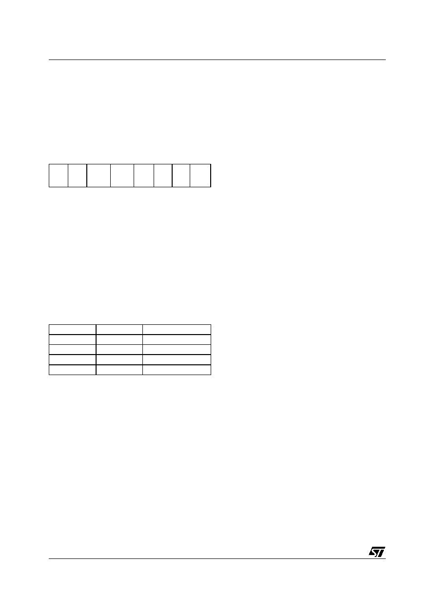
SMARTCARD INTERFACE CONTROL REGIS-
TER (CRDCR)
Read/Write
Reset Value: 0000 0000 (00h)
Bit 7 = CRDRST Smartcard Interface Reset.
This bit is set by software to reset the UART of the
Smartcard interface.
0: No Smartcard UART Reset
1: Smartcard UART Reset
Bit 6 = CRDDET Card Presence Detector.
This bit is set and cleared by software to configure
the card presence detector switch.
0: Switch open if no card is present
1: Switch closed if no card is present
Bits [5:4] = VCARD[1:0] Card voltage selection.
These bits select the card voltage.
Bit 3 = UART UART Mode Selection.
This bit is set and cleared by software to select
UART or manual mode.
0: CRDIO pin is a copy of the CRDIO bit in the
CRDCCR register (Manual mode).
1: CRDIO pin is the output of the smartcard UART
(UART mode).
Caution: Before switching from Manual mode to
UART mode, software must set the CRDIO bit in
the CRDCCR register.
Bit 2 = WTEN Waiting Time Counter enable.
0: Waiting Time counter stopped. While WTEN =
0, a write access to the CRDWT2 register loads
the Waiting time counter with the load value held
in the CRDWT0, CRDWT1 and CRDWT2 regis-
ters.
1: Start counter. In UART mode, the counter is au-
tomatically reloaded on start bit detection.
Bit 1 = CREP Automatic character repetition in
case of parity error.
0: In reception mode: no parity error signal indica-
tion (no retry on parity error).
In transmission mode: no error signal process-
ing. No retransmission of a refused character on
parity error.
1: Automatic parity management:
In transmission mode: up to 4 character repeti-
tions on parity error.
In reception mode: up to 4 retries are made on
parity error.
The PARF parity error flag is set by hardware if a
parity error is detected.
If the transmitted character is refused, the PARF
bit is set (but the TXCF bit is reset) and an interrupt
is generated if the PARM bit is set.
Note: If CREP=1, the PARF flag is set at the 5th
error (after 4 character repetitions or 4 retries).
If CREP=0, the PARF bit is set after the first parity
error.
Bit 0 = CONV ISO convention selection.
0: Direct convention, the B0 bit (LSB) is sent first, a
’1’ is a level 1 on the Card I/O pin, the parity bit is
added after the B7 bit.
1: Inverse convention, the B7 bit (MSB) is sent
first, a ’1’ is a level 0 on Card I/O pin, the parity
bit is added after the B0 bit.
Note: To detect the convention used by any card,
apply the following rule. If a card uses the conven-
tion selected by the reader, an RXC event occurs
at answer to reset. Otherwise a parity error also
occurs.
7
0
CRD
RST
CRD
DET
VCAR
D 1
VCAR
D 0
U
ART
WT
EN
C
REP
CO
NV
Bit 1
Bit 0
Vcard
0
0V
0
1
1.8V
1
0
3V
1
5V
相关PDF资料 |
PDF描述 |
|---|---|
| ST7SCR1T1/XXX | 8-BIT, MROM, 8 MHz, MICROCONTROLLER, PQFP64 |
| ST7SCR1E4U1/XXX | MICROCONTROLLER, QCC24 |
| ST7SCR1E4M1/XXX | 8-BIT, MROM, 8 MHz, MICROCONTROLLER, PDSO24 |
| ST7L34F2MCRE/XXX | 8-BIT, MROM, 8 MHz, MICROCONTROLLER, PDSO20 |
| ST7L35F2MARE/XXX | 8-BIT, MROM, 8 MHz, MICROCONTROLLER, PDSO20 |
相关代理商/技术参数 |
参数描述 |
|---|---|
| ST7FSCR1R4 | 制造商:STMICROELECTRONICS 制造商全称:STMicroelectronics 功能描述:8-BIT LOW-POWER, FULL-SPEED USB MCU WITH 16K FLASH, 768 RAM, SMARTCARD I/F, TIMER |
| ST7FSCR1R4T1 | 功能描述:8位微控制器 -MCU 8-BIT Lw Pwr USB MCU W/ 16K FLASH RoHS:否 制造商:Silicon Labs 核心:8051 处理器系列:C8051F39x 数据总线宽度:8 bit 最大时钟频率:50 MHz 程序存储器大小:16 KB 数据 RAM 大小:1 KB 片上 ADC:Yes 工作电源电压:1.8 V to 3.6 V 工作温度范围:- 40 C to + 105 C 封装 / 箱体:QFN-20 安装风格:SMD/SMT |
| ST7FUS-PRIMER | 功能描述:程序设计器 - 基于处理器 Low-Cost Eval Dev Tool Pack RoHS:否 制造商:Olimex Ltd. 产品:Programmers 工具用于评估:XMEGA, MegaAVR, tinyAVR 核心:AVR 接口类型:USB 工作电源电压:1.8 V to 5.5 V |
| ST7FUS-SK/RAIS | 制造商:STMicroelectronics 功能描述:Evaluation and Application Development with ST7Ultralite |
| ST7GEME4 | 制造商:STMICROELECTRONICS 制造商全称:STMicroelectronics 功能描述:Full-speed USB MCU with smartcard firmware and EMV/non-EMV interface |
发布紧急采购,3分钟左右您将得到回复。