- 您现在的位置:买卖IC网 > PDF目录69378 > ST7PL38F2MC/XXXE (STMICROELECTRONICS) 8-BIT, MROM, 8 MHz, MICROCONTROLLER, PDSO20 PDF资料下载
参数资料
| 型号: | ST7PL38F2MC/XXXE |
| 厂商: | STMICROELECTRONICS |
| 元件分类: | 微控制器/微处理器 |
| 英文描述: | 8-BIT, MROM, 8 MHz, MICROCONTROLLER, PDSO20 |
| 封装: | 0.300 INCH, ROHS COMPLIANT, PLASTIC, SOP-20 |
| 文件页数: | 110/168页 |
| 文件大小: | 2955K |
| 代理商: | ST7PL38F2MC/XXXE |
第1页第2页第3页第4页第5页第6页第7页第8页第9页第10页第11页第12页第13页第14页第15页第16页第17页第18页第19页第20页第21页第22页第23页第24页第25页第26页第27页第28页第29页第30页第31页第32页第33页第34页第35页第36页第37页第38页第39页第40页第41页第42页第43页第44页第45页第46页第47页第48页第49页第50页第51页第52页第53页第54页第55页第56页第57页第58页第59页第60页第61页第62页第63页第64页第65页第66页第67页第68页第69页第70页第71页第72页第73页第74页第75页第76页第77页第78页第79页第80页第81页第82页第83页第84页第85页第86页第87页第88页第89页第90页第91页第92页第93页第94页第95页第96页第97页第98页第99页第100页第101页第102页第103页第104页第105页第106页第107页第108页第109页当前第110页第111页第112页第113页第114页第115页第116页第117页第118页第119页第120页第121页第122页第123页第124页第125页第126页第127页第128页第129页第130页第131页第132页第133页第134页第135页第136页第137页第138页第139页第140页第141页第142页第143页第144页第145页第146页第147页第148页第149页第150页第151页第152页第153页第154页第155页第156页第157页第158页第159页第160页第161页第162页第163页第164页第165页第166页第167页第168页
Obsolete
Product(s)
- Obsolete
Product(s)
ST7L34, ST7L35, ST7L38, ST7L39
46/168
10 I/O PORTS
10.1 INTRODUCTION
The I/O ports allow data transfer. An I/O port can
contain up to 8 pins. Each pin can be programmed
independently either as a digital input or digital
output. In addition, specific pins may have several
other functions. These functions can include exter-
nal interrupt, alternate signal input/output for on-
chip peripherals or analog input.
10.2 FUNCTIONAL DESCRIPTION
A Data Register (DR) and a Data Direction Regis-
ter (DDR) are always associated with each port.
The Option Register (OR), which allows input/out-
put options, may or may not be implemented. The
following description takes into account the OR
register. Refer to the Port Configuration table for
device specific information.
An I/O pin is programmed using the corresponding
bits in the DDR, DR and OR registers: Bit x corre-
sponding to pin x of the port.
Figure 31 shows the generic I/O block diagram.
10.2.1 Input Modes
Clearing the DDRx bit selects input mode. In this
mode, reading its DR bit returns the digital value
from that I/O pin.
If an OR bit is available, different input modes can
be configured by software: Floating or pull-up. Re-
fer to I/O Port Implementation section for configu-
ration.
Notes:
1. Writing to the DR modifies the latch value but
does not change the state of the input pin.
2. Do not use read/modify/write instructions
(BSET/BRES) to modify the DR register.
External Interrupt Function
Depending on the device, setting the ORx bit while
in input mode can configure an I/O as an input with
interrupt. In this configuration, a signal edge or lev-
el input on the I/O generates an interrupt request
via the corresponding interrupt vector (eix).
Falling or rising edge sensitivity is programmed in-
dependently for each interrupt vector. The Exter-
nal Interrupt Control Register (EICR) or the Miscel-
laneous Register controls this sensitivity, depend-
ing on the device.
Each external interrupt vector is linked to a dedi-
cated group of I/O port pins (see pinout description
in section 2 on page 7 and interrupt section).
If several I/O interrupt pins on the same interrupt
vector are selected simultaneously, they are logi-
cally combined. For this reason if one of the inter-
rupt pins is tied low, it may mask the others.
External interrupts are hardware interrupts. Fetch-
ing the corresponding interrupt vector automatical-
ly clears the request latch. Modifying the sensitivity
bits will clear any pending interrupts.
10.2.2 Output Modes
Setting the DDRx bit selects output mode. Writing
to the DR bits applies a digital value to the I/O
through the latch. Reading the DR bits returns the
previously stored value.
If an OR bit is available, different output modes
can be selected by software: Push-pull or open-
drain. Refer to I/O Port Implementation section for
configuration.
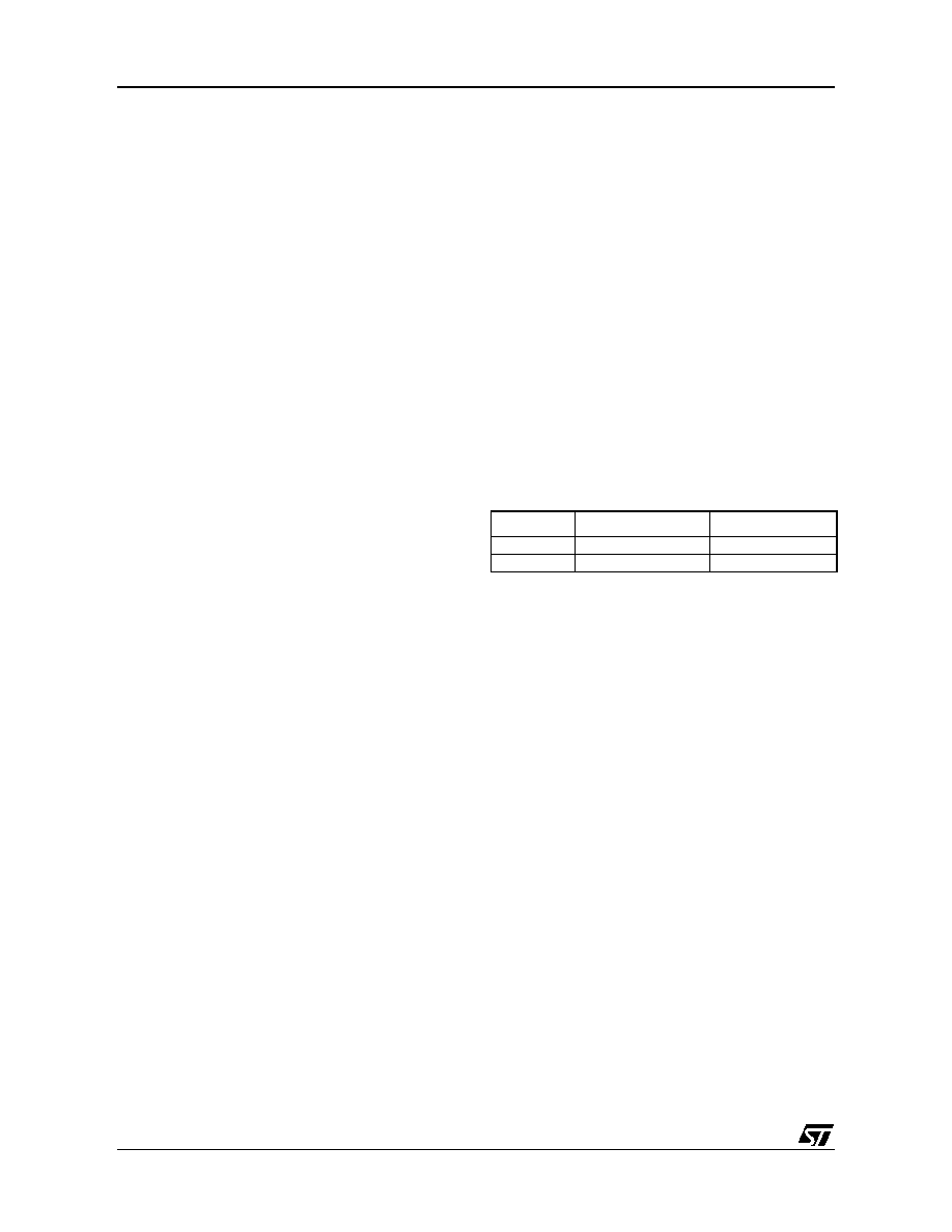
DR Value and Output Pin Status
10.2.3 Alternate Functions
Many ST7s I/Os have one or more alternate func-
tions. These may include output signals from, or
input signals to, on-chip peripherals. The Device
Pin Description table describes which peripheral
signals can be input/output to which ports.
A signal coming from an on-chip peripheral can be
output on an I/O. To do this, enable the on-chip
peripheral as an output (enable bit in the peripher-
al’s control register). The peripheral configures the
I/O as an output and takes priority over standard I/
O programming. The I/O’s state is readable by ad-
dressing the corresponding I/O data register.
Configuring an I/O as floating enables alternate
function input. It is not recommended to configure
an I/O as pull-up as this will increase current con-
sumption. Before using an I/O as an alternate in-
put, configure it without interrupt. Otherwise spuri-
ous interrupts can occur.
Configure an I/O as input floating for an on-chip
peripheral signal which can be input and output.
Caution: I/Os which can be configured as both an
analog and digital alternate function need special
attention. The user must control the peripherals so
that the signals do not arrive at the same time on
the same pin. If an external clock is used, only the
clock alternate function should be employed on
that I/O pin and not the other alternate function.
DR
Push-Pull
Open-Drain
0VOL
VOL
1VOH
Floating
1
相关PDF资料 |
PDF描述 |
|---|---|
| ST7PL38F2UCXXXRE | 8-BIT, MROM, 8 MHz, MICROCONTROLLER, QCC20 |
| ST7PL39F2MA/XXXE | 8-BIT, MROM, 8 MHz, MICROCONTROLLER, PDSO20 |
| ST7L38F2UC/XXXE | 8-BIT, MROM, 8 MHz, MICROCONTROLLER, QCC20 |
| ST7FL38F2UATRE | 8-BIT, FLASH, 8 MHz, MICROCONTROLLER, QCC20 |
| ST7PL35F2MAXXXRE | 8-BIT, MROM, 8 MHz, MICROCONTROLLER, PDSO20 |
相关代理商/技术参数 |
参数描述 |
|---|---|
| ST7PLITE02F0U6TR | 制造商:STMICROELECTRONICS 制造商全称:STMicroelectronics 功能描述:8-BIT MICROCONTROLLER WITH SINGLE VOLTAGE FLASH MEMORY, DATA EEPROM, ADC, TIMERS, SPI |
| ST7PLITE02Y0B6 | 制造商:STMICROELECTRONICS 制造商全称:STMicroelectronics 功能描述:8-BIT MICROCONTROLLER WITH SINGLE VOLTAGE FLASH MEMORY, DATA EEPROM, ADC, TIMERS, SPI |
| ST7PLITE02Y0B6TR | 制造商:STMICROELECTRONICS 制造商全称:STMicroelectronics 功能描述:8-bit microcontroller with single voltage Flash memory, data EEPROM, ADC, timers, SPI |
| ST7PLITE02Y0M6 | 制造商:STMICROELECTRONICS 制造商全称:STMicroelectronics 功能描述:8-bit microcontroller with single voltage Flash memory, data EEPROM, ADC, timers, SPI |
| ST7PLITE02Y0M6TR | 制造商:STMICROELECTRONICS 制造商全称:STMicroelectronics 功能描述:8-bit microcontroller with single voltage Flash memory, data EEPROM, ADC, timers, SPI |
发布紧急采购,3分钟左右您将得到回复。