- 您现在的位置:买卖IC网 > PDF目录68560 > W989D6CBGX7E (WINBOND ELECTRONICS CORP) 32M X 16 DDR DRAM, 5.4 ns, PBGA54 PDF资料下载
参数资料
| 型号: | W989D6CBGX7E |
| 厂商: | WINBOND ELECTRONICS CORP |
| 元件分类: | DRAM |
| 英文描述: | 32M X 16 DDR DRAM, 5.4 ns, PBGA54 |
| 封装: | 8 X 9 MM, 0.80 MM PITCH, HALOGEN FREE AND LEAD FREE, VFBGA-54 |
| 文件页数: | 5/67页 |
| 文件大小: | 1469K |
| 代理商: | W989D6CBGX7E |
第1页第2页第3页第4页当前第5页第6页第7页第8页第9页第10页第11页第12页第13页第14页第15页第16页第17页第18页第19页第20页第21页第22页第23页第24页第25页第26页第27页第28页第29页第30页第31页第32页第33页第34页第35页第36页第37页第38页第39页第40页第41页第42页第43页第44页第45页第46页第47页第48页第49页第50页第51页第52页第53页第54页第55页第56页第57页第58页第59页第60页第61页第62页第63页第64页第65页第66页第67页
W989D6CB / W989D2CB
512Mb Mobile LPSDR
Publication Release Date: Jun, 27, 2011
- 13 -
Revision A01-004
Note :
1.
Conditions outside the limits listed under
“ABSOLUTE MAXIMUM RATINGS” may cause permanent damage to the device.
Exposure to
“ABSOLUTE MAXIMUM RATINGS” conditions for extended periods may affect deice reliability.
2.
All voltages are referenced to VSS and VSSQ.
3.
These parameters depend on the cycle rate. These values are measured at a cycle rate with the minimum values of tCK and tRC .
Input signals transition once per tCK period.
4.
These parameters depend on the output loading. Specified values are obtained with the output open.
5.
Power-up sequence is described in Note 9.
6.
AC TEST CONDITIONS : (refer to 6.6.2)
7.
tHZ defines the time at which the outputs achieve the open circuit condition and is not referenced to output voltage
levels.
8.
These parameters account for the number of clock cycles and depend on the operating frequency of the clock, as
follows: The number of clock cycles = specified value of timing / clock period (count fractions as a whole number)
9.
Power up Sequence : The SDRAM should be powered up by the following sequence of operations.
a.
Power must be applied to VDD before or at the same time as VDDQ while all input signals are held in the
“NOP” state. The
CLK signal will be applied at power up with power.
b.
After power-up a pause of at least 200 uA is required. It is required that DQM and CKE signals must be held
“High” (VDD
levels ) to ensure that the DQ output is in High-impedance state.
c.
All banks must be precharged.
d.
The Mode Register Set command must be issued to initialize the Mode Register.
e.
The Extended Mode Register Set command must be issued to initialize the Extended Mode Register.
f.
Issue two or more Auto Refresh dummy cycles to stabilize the internal circuitry of the device.
The Mode Register Set command can be invoked either before or after the Auto Refresh dummy cycles.
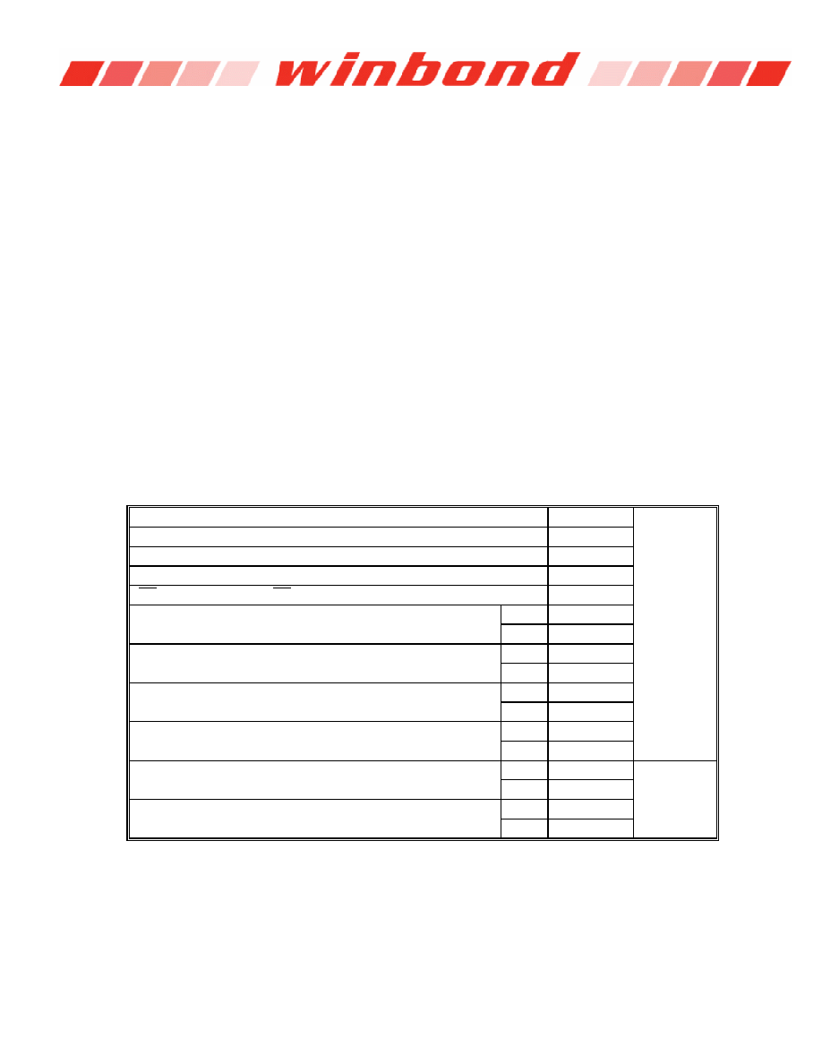
6.6.3 AC Latency Characteristics
CKE to clock disable (CKE Latency)
1
Cycle
DQM to output in High-Z (Read DQM Latency)
2
DQM to input data delay (Write DQM Latency)
0
Write command to input data (Write Data Latency)
0
CS to Command input ( CS Latency)
0
Precharge to DQ Hi-Z Lead time
CL = 2
2
CL = 3
3
Precharge to Last Valid data out
CL = 2
1
CL = 3
2
Burst Stop Command to DQ Hi-Z Lead time
CL = 2
2
CL = 3
3
Burst Stop Command to Last Valid data out
CL = 2
1
CL = 3
2
Read with Auto Precharge Command to Active/Ref Command
CL = 2
BL+ tRP
Cycle + ns
CL = 3
BL+ tRP
Write with Auto Precharge Command to Active/Ref Command
CL = 2
BL+1 + tRP
CL = 3
BL+1 + tRP
相关PDF资料 |
PDF描述 |
|---|---|
| W99802G | SPECIALTY TELECOM CIRCUIT, PBGA184 |
| WAC-011-A | TRANSCEIVER, PQFP100 |
| WAC-011-A | TRANSCEIVER, PQFP100 |
| WAC-021-C | ATM SEGMENTATION AND REASSEMBLY DEVICE, PQFP240 |
| WAC-021-C | ATM SEGMENTATION AND REASSEMBLY DEVICE, PQFP240 |
相关代理商/技术参数 |
参数描述 |
|---|---|
| W989D6CBGX7G | 制造商:WINBOND 制造商全称:Winbond 功能描述:512Mb Mobile LPSDR |
| W989D6KBGX7E | 制造商:Winbond Electronics Corp 功能描述:IC LPSDR SDRAM 512MBIT 54VFBGA |
| W98AD2KBJX6E | 制造商:Winbond Electronics Corp 功能描述:IC MEMORY SDRAM 1GB 90VFBGA |
| W98AD2KBJX6I | 制造商:Winbond Electronics Corp 功能描述:IC MEMORY SDRAM 1GB 90VFBGA |
| W98M9640 | 制造商:未知厂家 制造商全称:未知厂家 功能描述:Semiconductor Discrete Device, P-Channel Power MOS Field Effect Transistor |
发布紧急采购,3分钟左右您将得到回复。