- 您现在的位置:买卖IC网 > PDF目录11831 > XR16C2852IJTR-F (Exar Corporation)IC UART FIFO 128B 44PLCC PDF资料下载
参数资料
| 型号: | XR16C2852IJTR-F |
| 厂商: | Exar Corporation |
| 文件页数: | 20/51页 |
| 文件大小: | 0K |
| 描述: | IC UART FIFO 128B 44PLCC |
| 标准包装: | 500 |
| 特点: | * |
| 通道数: | 2,DUART |
| FIFO's: | 128 字节 |
| 规程: | RS232,RS485 |
| 电源电压: | 2.97 V ~ 5.5 V |
| 带自动流量控制功能: | 是 |
| 带IrDA 编码器/解码器: | 是 |
| 带故障启动位检测功能: | 是 |
| 带调制解调器控制功能: | 是 |
| 带CMOS: | 是 |
| 安装类型: | 表面贴装 |
| 封装/外壳: | 44-LCC(J 形引线) |
| 供应商设备封装: | 44-PLCC(16.59x16.59) |
| 包装: | 带卷 (TR) |
第1页第2页第3页第4页第5页第6页第7页第8页第9页第10页第11页第12页第13页第14页第15页第16页第17页第18页第19页当前第20页第21页第22页第23页第24页第25页第26页第27页第28页第29页第30页第31页第32页第33页第34页第35页第36页第37页第38页第39页第40页第41页第42页第43页第44页第45页第46页第47页第48页第49页第50页第51页
xr
XR16C2852
REV. 2.1.1
2.97V TO 5.5V DUAL UART WITH 128-BYTE FIFOS
27
FCR[3]: DMA Mode Select
Controls the behavior of the TXRDY# and RXRDY# pins. See DMA operation section for details.
Logic 0 = Normal Operation (default).
Logic 1 = DMA Mode.
FCR[5:4]: Transmit FIFO Trigger Select
(logic 0 = default, TX trigger level = 1)
These 2 bits set the trigger level for the transmit FIFO. The UART will issue a transmit interrupt when the
number of characters in the FIFO falls below the selected trigger level, or when it gets empty in case that the
FIFO did not get filled over the trigger level on last re-load. Table 10 below shows the selections. EFR bit-4
must be set to ‘1’ before these bits can be accessed. Note that the receiver and the transmitter cannot use
different trigger tables. Whichever selection is made last applies to both the RX and TX side.
FCR[7:6]: Receive FIFO Trigger Select
(logic 0 = default, RX trigger level =1)
The FCTR Bits 5-4 are associated with these 2 bits. These 2 bits are used to set the trigger level for the receive
FIFO. The UART will issue a receive interrupt when the number of the characters in the FIFO crosses the
trigger level. Table 10 shows the complete selections. Note that the receiver and the transmitter cannot use
different trigger tables. Whichever selection is made last applies to both the RX and TX side.
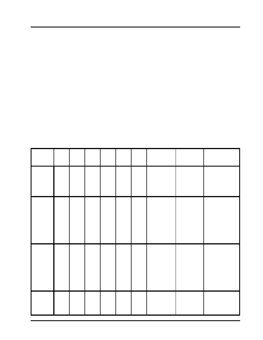
TABLE 10: TRANSMIT AND RECEIVE FIFO TRIGGER TABLE AND LEVEL SELECTION
TRIGGER
TABLE
FCTR
BIT-5
FCTR
BIT-4
FCR
BIT-7
FCR
BIT-6
FCR
BIT-5
FCR
BIT
-4
RECEIVE
TRIGGER LEVEL
TRANSMIT
TRIGGER
LEVEL
COMPATIBILITY
Table-A
0
1
0
1
0
1
0
1 (default)
4
8
14
1 (default)
16C550, 16C2550,
16C2552, 16C554,
16C580
Table-B
0
1
0
1
0
1
0
1
0
1
0
1
0
1
8
16
24
28
16
8
24
30
16C650A
Table-C
1
0
1
0
1
0
1
0
1
0
1
0
1
8
16
56
60
8
16
32
56
16C654
Table-D
1
X
Programmable
via TRG
register.
FCTR[7] = 0.
Programmable
via TRG
register.
FCTR[7] = 1.
16L2752, 16L2750,
16C2850, 16C850,
16C854, 16C864
相关PDF资料 |
PDF描述 |
|---|---|
| XR16C2850IJTR-F | IC UART FIFO 128B 44PLCC |
| XR16V554IV-F | IC UART FIFO 16B QUAD 64LQFP |
| VE-B5L-IW-F1 | CONVERTER MOD DC/DC 28V 100W |
| VE-B5L-IX-F4 | CONVERTER MOD DC/DC 28V 75W |
| VE-B5L-IX-F2 | CONVERTER MOD DC/DC 28V 75W |
相关代理商/技术参数 |
参数描述 |
|---|---|
| XR-16C450CJ | 制造商:未知厂家 制造商全称:未知厂家 功能描述:UART |
| XR-16C450CP | 制造商:未知厂家 制造商全称:未知厂家 功能描述:UART |
| XR-16C452CJ | 制造商:未知厂家 制造商全称:未知厂家 功能描述:UART |
| XR-16C550CJ | 制造商:未知厂家 制造商全称:未知厂家 功能描述:UART |
| XR-16C550CP | 制造商:未知厂家 制造商全称:未知厂家 功能描述:UART |
发布紧急采购,3分钟左右您将得到回复。