- 您现在的位置:买卖IC网 > PDF目录11831 > XR16C2852IJTR-F (Exar Corporation)IC UART FIFO 128B 44PLCC PDF资料下载
参数资料
| 型号: | XR16C2852IJTR-F |
| 厂商: | Exar Corporation |
| 文件页数: | 23/51页 |
| 文件大小: | 0K |
| 描述: | IC UART FIFO 128B 44PLCC |
| 标准包装: | 500 |
| 特点: | * |
| 通道数: | 2,DUART |
| FIFO's: | 128 字节 |
| 规程: | RS232,RS485 |
| 电源电压: | 2.97 V ~ 5.5 V |
| 带自动流量控制功能: | 是 |
| 带IrDA 编码器/解码器: | 是 |
| 带故障启动位检测功能: | 是 |
| 带调制解调器控制功能: | 是 |
| 带CMOS: | 是 |
| 安装类型: | 表面贴装 |
| 封装/外壳: | 44-LCC(J 形引线) |
| 供应商设备封装: | 44-PLCC(16.59x16.59) |
| 包装: | 带卷 (TR) |
第1页第2页第3页第4页第5页第6页第7页第8页第9页第10页第11页第12页第13页第14页第15页第16页第17页第18页第19页第20页第21页第22页当前第23页第24页第25页第26页第27页第28页第29页第30页第31页第32页第33页第34页第35页第36页第37页第38页第39页第40页第41页第42页第43页第44页第45页第46页第47页第48页第49页第50页第51页
xr
XR16C2852
REV. 2.1.1
2.97V TO 5.5V DUAL UART WITH 128-BYTE FIFOS
3
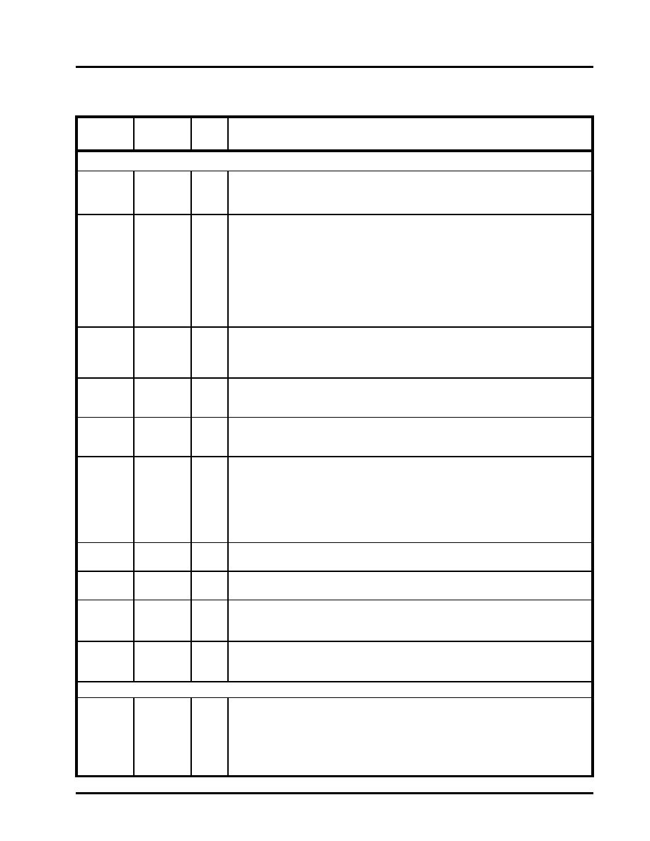
PIN DESCRIPTIONS
Pin Description
NAME
44-PLCC
PIN #
TYPE
DESCRIPTION
DATA BUS INTERFACE
A2
A1
A0
15
14
10
I
Address data lines [2:0]. These 3 address lines select one of the internal registers in
UART channel A/B during a data bus transaction.
D7
D6
D5
D4
D3
D2
D1
D0
9
8
7
6
5
4
3
2
I/O
Data bus lines [7:0] (bidirectional).
IOR#
24
I
Input/Output Read Strobe (active low). The falling edge instigates an internal read
cycle and retrieves the data byte from an internal register pointed to by the address
lines [A2:A0]. The data byte is placed on the data bus to allow the host processor to
read it on the rising edge.
IOW#
20
I
Input/Output Write Strobe (active low). The falling edge instigates an internal write
cycle and the rising edge transfers the data byte on the data bus to an internal regis-
ter pointed by the address lines.
CS#
18
I
UART chip select (active low). This function selects channel A or B in accordance
with the logical state of the CHSEL pin. This allows data to be transferred between the
user CPU and the 2852.
CHSEL
16
I
Channel Select - UART channel A or B is selected by the logical state of this pin when
the CS# pin is LOW. A LOW on the CHSEL selects the UART channel B while a HIGH
selects UART channel A. Normally, CHSEL could just be an address line from the
user CPU such as A4. Bit-0 of the Alternate Function Register (AFR) can temporarily
override CHSEL function, allowing the user to write to both channel register simulta-
neously with one write cycle when CS# is LOW. It is especially useful during the ini-
tialization routine.
INTA
34
O
UART channel A Interrupt output (active high). A logic high indicates channel A is
requesting for service. For more details, see
INTB
17
O
UART channel B Interrupt output (active high). A logic high indicates channel B is
requesting for service. For more details, see
TXRDYA#
1
O
UART channel A Transmitter Ready (active low). The output provides the TX
FIFO/THR status for transmit channel A. See Table 2 on page 9. If this output is
not used, leave it unconnected.
TXRDYB#
32
O
UART channel B Transmitter Ready (active low). The output provides the TX FIFO/
THR status for transmit channel B.
See Table 2 on page 9. If this output is not
used, leave it unconnected.
MODEM OR SERIAL I/O INTERFACE
TXA
38
O
UART channel A Transmit Data or infrared encoder data. Standard transmit and
receive interface is enabled when MCR[6] = 0. In this mode, the TX signal will be
HIGH during reset or idle (no data). Infrared IrDA transmit and receive interface is
enabled when MCR[6] = 1. In the Infrared mode, the inactive state (no data) for the
Infrared encoder/decoder interface is a logic 0. If this output is not used, leave it
unconnected.
相关PDF资料 |
PDF描述 |
|---|---|
| XR16C2850IJTR-F | IC UART FIFO 128B 44PLCC |
| XR16V554IV-F | IC UART FIFO 16B QUAD 64LQFP |
| VE-B5L-IW-F1 | CONVERTER MOD DC/DC 28V 100W |
| VE-B5L-IX-F4 | CONVERTER MOD DC/DC 28V 75W |
| VE-B5L-IX-F2 | CONVERTER MOD DC/DC 28V 75W |
相关代理商/技术参数 |
参数描述 |
|---|---|
| XR-16C450CJ | 制造商:未知厂家 制造商全称:未知厂家 功能描述:UART |
| XR-16C450CP | 制造商:未知厂家 制造商全称:未知厂家 功能描述:UART |
| XR-16C452CJ | 制造商:未知厂家 制造商全称:未知厂家 功能描述:UART |
| XR-16C550CJ | 制造商:未知厂家 制造商全称:未知厂家 功能描述:UART |
| XR-16C550CP | 制造商:未知厂家 制造商全称:未知厂家 功能描述:UART |
发布紧急采购,3分钟左右您将得到回复。