- 您现在的位置:买卖IC网 > PDF目录11831 > XR16C2852IJTR-F (Exar Corporation)IC UART FIFO 128B 44PLCC PDF资料下载
参数资料
| 型号: | XR16C2852IJTR-F |
| 厂商: | Exar Corporation |
| 文件页数: | 5/51页 |
| 文件大小: | 0K |
| 描述: | IC UART FIFO 128B 44PLCC |
| 标准包装: | 500 |
| 特点: | * |
| 通道数: | 2,DUART |
| FIFO's: | 128 字节 |
| 规程: | RS232,RS485 |
| 电源电压: | 2.97 V ~ 5.5 V |
| 带自动流量控制功能: | 是 |
| 带IrDA 编码器/解码器: | 是 |
| 带故障启动位检测功能: | 是 |
| 带调制解调器控制功能: | 是 |
| 带CMOS: | 是 |
| 安装类型: | 表面贴装 |
| 封装/外壳: | 44-LCC(J 形引线) |
| 供应商设备封装: | 44-PLCC(16.59x16.59) |
| 包装: | 带卷 (TR) |
第1页第2页第3页第4页当前第5页第6页第7页第8页第9页第10页第11页第12页第13页第14页第15页第16页第17页第18页第19页第20页第21页第22页第23页第24页第25页第26页第27页第28页第29页第30页第31页第32页第33页第34页第35页第36页第37页第38页第39页第40页第41页第42页第43页第44页第45页第46页第47页第48页第49页第50页第51页
xr
XR16C2852
REV. 2.1.1
2.97V TO 5.5V DUAL UART WITH 128-BYTE FIFOS
13
2.12
Receiver
The receiver section contains an 8-bit Receive Shift Register (RSR) and 128 bytes of FIFO which includes a
byte-wide Receive Holding Register (RHR). The RSR uses the 16X for timing. It verifies and validates every bit
on the incoming character in the middle of each data bit. On the falling edge of a start or false start bit, an
internal receiver counter starts counting at the 16X. After 8 clocks the start bit period should be at the center of
the start bit. At this time the start bit is sampled and if it is still a logic 0 it is validated. Evaluating the start bit in
this manner prevents the receiver from assembling a false character. The rest of the data bits and stop bits are
sampled and validated in this same manner to prevent false framing. If there were any error(s), they are
reported in the LSR register bits 2-4. Upon unloading the receive data byte from RHR, the receive FIFO pointer
is bumped and the error tags are immediately updated to reflect the status of the data byte in RHR register.
RHR can generate a receive data ready interrupt upon receiving a character or delay until it reaches the FIFO
trigger level. Furthermore, data delivery to the host is guaranteed by a receive data ready time-out interrupt
when data is not received for 4 word lengths as defined by LCR[1:0] plus 12 bits time. This is equivalent to 3.7-
4.6 character times. The RHR interrupt is enabled by IER bit-0.
2.12.1
Receive Holding Register (RHR) - Read-Only
The Receive Holding Register is an 8-bit register that holds a receive data byte from the Receive Shift
Register. It provides the receive data interface to the host processor. The RHR register is part of the receive
FIFO of 128 bytes by 11-bits wide, the 3 extra bits are for the 3 error tags to be reported in LSR register. When
the FIFO is enabled by FCR bit-0, the RHR contains the first data character received by the FIFO. After the
RHR is read, the next character byte is loaded into the RHR and the errors associated with the current data
byte are immediately updated in the LSR bits 2-4.
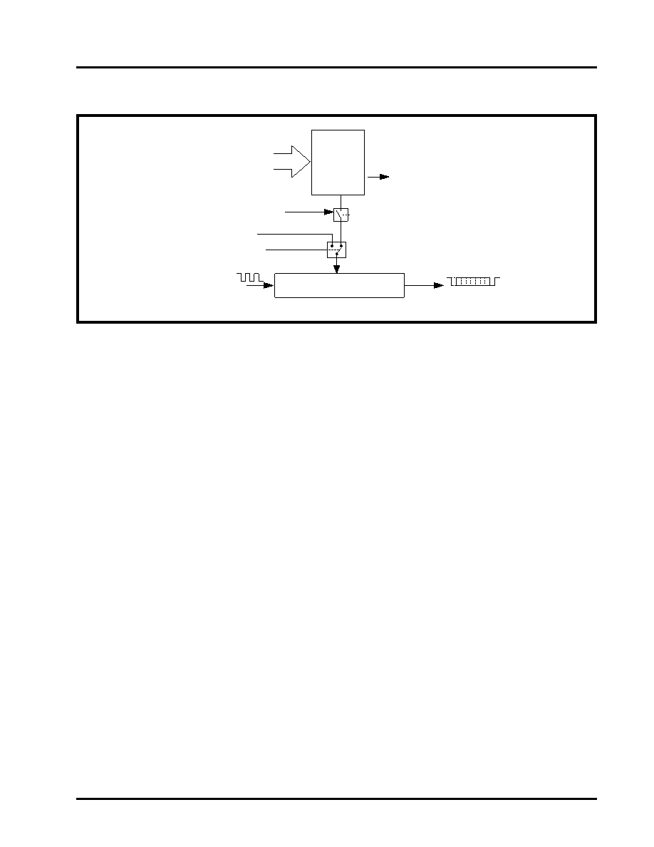
FIGURE 8. TRANSMITTER OPERATION IN FIFO AND FLOW CONTROL MODE
Transmit Data Shift Register
(TSR)
Transmit
Data Byte
THR Interrupt (ISR bit-1) falls
below the programmed Trigger
Level and then when becomes
empty. FIFO is Enabled by FCR
bit-0=1
Transmit
FIFO
16X Clock
Auto CTS Flow Control (CTS# pin)
Auto Software Flow Control
Flow Control Characters
(Xoff1/2 and Xon1/2 Reg.
TXFIFO 1
相关PDF资料 |
PDF描述 |
|---|---|
| XR16C2850IJTR-F | IC UART FIFO 128B 44PLCC |
| XR16V554IV-F | IC UART FIFO 16B QUAD 64LQFP |
| VE-B5L-IW-F1 | CONVERTER MOD DC/DC 28V 100W |
| VE-B5L-IX-F4 | CONVERTER MOD DC/DC 28V 75W |
| VE-B5L-IX-F2 | CONVERTER MOD DC/DC 28V 75W |
相关代理商/技术参数 |
参数描述 |
|---|---|
| XR-16C450CJ | 制造商:未知厂家 制造商全称:未知厂家 功能描述:UART |
| XR-16C450CP | 制造商:未知厂家 制造商全称:未知厂家 功能描述:UART |
| XR-16C452CJ | 制造商:未知厂家 制造商全称:未知厂家 功能描述:UART |
| XR-16C550CJ | 制造商:未知厂家 制造商全称:未知厂家 功能描述:UART |
| XR-16C550CP | 制造商:未知厂家 制造商全称:未知厂家 功能描述:UART |
发布紧急采购,3分钟左右您将得到回复。