参数资料
| 型号: | ZL6105ALAFTR5546 |
| 厂商: | Intersil |
| 文件页数: | 21/35页 |
| 文件大小: | 0K |
| 描述: | IC REG CTRLR BUCK PWM VM 36-QFN |
| 标准包装: | 100 |
| PWM 型: | 电压模式 |
| 输出数: | 1 |
| 频率 - 最大: | 1.4MHz |
| 占空比: | 95% |
| 电源电压: | 3 V ~ 14 V |
| 降压: | 是 |
| 升压: | 无 |
| 回扫: | 无 |
| 反相: | 无 |
| 倍增器: | 无 |
| 除法器: | 无 |
| Cuk: | 无 |
| 隔离: | 无 |
| 工作温度: | -40°C ~ 85°C |
| 封装/外壳: | 36-VFQFN 裸露焊盘 |
| 包装: | 托盘 |
第1页第2页第3页第4页第5页第6页第7页第8页第9页第10页第11页第12页第13页第14页第15页第16页第17页第18页第19页第20页当前第21页第22页第23页第24页第25页第26页第27页第28页第29页第30页第31页第32页第33页第34页第35页
�� �
�
�ZL6105�
�---------------------� (� in%� )� ≤� ---------------------------------------�
�Vin� Nom�
�256� ?� Vout� (EQ.� 31)�
�Vin� Nom�
�Loop� Compensation�
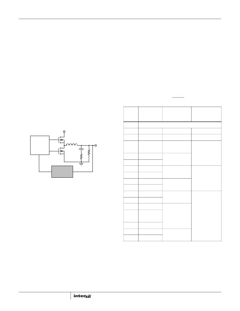
�The� ZL6105� operates� as� a� voltage-mode� synchronous� buck�
�controller� with� a� fixed� frequency� PWM� scheme.� Although� the�
�ZL6105� uses� a� digital� control� loop,� it� operates� much� like� a�
�traditional� analog� PWM� controller.� Figure� 13� is� a� simplified� block�
�diagram� of� the� ZL6105� control� loop,� which� differs� from� an�
�analog� control� loop� only� by� the� constants� in� the� PWM� and�
�compensation� blocks.� As� in� the� analog� controller� case,� the�
�compensation� block� compares� the� output� voltage� to� the� desired�
�voltage� reference� and� compensates� to� keep� the� loop� stable.� The�
�resulting� integrated� error� signal� is� used� to� drive� the� PWM� logic,�
�converting� the� error� signal� to� a� duty� cycle� to� drive� the� external�
�MOSFETs.�
�The� ZL6105� has� an� auto� compensation� feature� that� measures�
�the� characteristics� of� the� power� train� and� calculates� the� proper�
�tap� coefficients.� Auto� compensation� is� configured� using� the� FC0�
�and� FC1� pins� as� shown� in� Table� 16� and� Table� 17.�
�When� auto� compensation� is� enabled,� the� routine� can� be� set� to�
�execute� one� time� after� ramp� or� periodically� while� regulating.�
�Note� that� the� Auto� Compensation� feature� requires� a� minimum�
�immediately� after� the� first� Auto� Comp� cycle� completes�
�(POWER_GOOD_DELAY� will� be� ignored).�
�The� Auto� Comp� Gain� control� scales� the� Auto� Comp� results� to�
�allow� a� trade-off� between� transient� response� and� steady-state�
�duty� cycle� jitter.� A� setting� of� 100%� will� provide� the� fastest�
�transient� response� while� a� setting� of� 10%� will� produce� the� lowest�
�jitter.�
�Note� that� if� Auto� Comp� is� enabled,� for� best� results� Vin� must� be�
�stable� before� Auto� Comp� begins,� as� shown� in� Equation� 31.�
�Δ� Vin� 100%�
�1� +� -----------------------------�
�The� auto� compensation� function� can� also� be� configured� via� the�
�AUTO_COMP_CONFIG� command� and� controlled� using� the�
�AUTO_COMP_CONTROL� command� over� the� I� 2� C/SMBus� interface.�
�Please� refer� to� Application� Note� AN2033� for� further� details.�
�TABLE� 16.� FC0� PIN-STRAP� SETTINGS�
��FC0� PIN�
�STORE� VALUES�
�SINGLE/REPEAT�
�PG� ASSERT�
��V� IN�
�LOW�
�OPEN�
�Not� Stored�
�Auto� Comp� Disabled�
�Single�
�After� Auto� Comp�
�DPWM�
�D�
�1-D�
�L�
�C�
�R� C�
�R� O�
�V� OUT�
�HIGH�
�10k� ?�
�11k� ?�
�12.1k� ?�
�Store� in� Flash�
�Not� Stored�
�Store� in� Flash�
�Not� Stored�
�Single�
�Single�
�Repeat� ~1� sec�
�After� Auto� Comp�
�After� Auto� Comp�
�13.3k� ?�
�Store� in� Flash�
�Compensation�
�14.7k� ?�
�Not� Stored�
�Single�
�FIGURE� 13.� CONTROL� LOOP� BLOCK� DIAGRAM�
�If� the� device� is� configured� to� store� auto� comp� values,� the�
�calculated� compensation� values� will� be� saved� in� the� Auto� Comp�
�Store� and� may� be� read� back� through� the� PID_TAPS� command.� If�
�repeat� mode� is� enabled,� the� first� Auto� Comp� results� after� the� first�
�ramp� will� be� stored;� the� values� calculated� periodically� are� not�
�stored� in� the� Auto� Comp� Store.� When� compensation� values� are�
�saved� in� the� Auto� Comp� Store,� the� device� will� use� those�
�compensation� values� on� subsequent� ramps.� In� repeat� mode,� the�
�latest� Auto� Comp� results� will� always� be� used� during� operation.�
�Stored� Auto� Comp� results� can� only� be� cleared� by� disabling� Auto�
�Comp� Store,� which� is� not� permitted� while� the� output� is� enabled.�
�However,� sending� the� AUTOCOMP_CONTROL� command� while�
�enabled� in� Store� mode� will� cause� the� next� results� to� be� stored,�
�16.2k� ?�
�17.8k� ?�
�19.6k� ?�
�21.5k� ?�
�23.7k� ?�
�26.1k� ?�
�28.7k� ?�
�31.6k� ?�
�34.8k� ?�
�38.3k� ?�
�42.2k� ?�
�Store� in� Flash�
�Not� Stored�
�Store� in� Flash�
�Not� Stored�
�Store� in� Flash�
�Not� Stored�
�Store� in� Flash�
�Not� Stored�
�Store� in� Flash�
�Not� Stored�
�Store� in� Flash�
�Repeat� ~1� sec�
�Single�
�Repeat� ~1� min�
�Single�
�Repeat� ~1� min�
�After� PG� Delay�
�After� Auto� Comp�
�After� PG� Delay�
�overwriting� previously� stored� values.� If� auto� compensation� is�
�disabled,� the� device� will� use� the� compensation� parameters� that�
�are� stored� in� the� DEFAULT_STORE� or� USER_STORE.�
�If� the� PG� Assert� parameter� is� set� to� "Use� PG� Delay,"� PG� will� be� asserted�
�according� to� the� POWER_GOOD_DELAY� command,� after� which� Auto�
�Comp� will� begin.� When� Auto� Comp� is� enabled,� the� user� must� not�
�program� a� Power-Good� Delay� that� will� expire� before� the� ramp� is�
�finished.� If� PG� Assert� is� set� to� "After� Auto� Comp,"� PG� will� be� asserted�
�21�
�FN6906.5�
�December� 19,� 2013�
�相关PDF资料 |
PDF描述 |
|---|---|
| ZLDO1117G25TA | IC REG LDO 2.5V 1A SOT223-3 |
| ZLDO330T8TA | IC REG LDO 3.3V .3A SOT223-8 |
| ZLDO485T8TA | IC REG LDO 4.85V .3A SOT223-8 |
| ZLDO500T8TA | IC REG LDO 5V .3A SOT223-8 |
| ZM331643GTC | IC MONITOR 2.68V SUPPLY SOT223 |
相关代理商/技术参数 |
参数描述 |
|---|---|
| ZL62034UBJA | 制造商:TE Connectivity 功能描述:4x6.25 Gb/s TIA/LA Receiver D |
| ZL62B | 制造商:YEASHIN 制造商全称:YEASHIN 功能描述:500 mW DO-35 Hermetically Sealed Glass Zener Voltage Regulators |
| ZL68B | 制造商:YEASHIN 制造商全称:YEASHIN 功能描述:500 mW DO-35 Hermetically Sealed Glass Zener Voltage Regulators |
| ZL6V2B | 制造商:YEASHIN 制造商全称:YEASHIN 功能描述:500 mW DO-35 Hermetically Sealed Glass Zener Voltage Regulators |
| ZL6V8B | 制造商:YEASHIN 制造商全称:YEASHIN 功能描述:500 mW DO-35 Hermetically Sealed Glass Zener Voltage Regulators |
发布紧急采购,3分钟左右您将得到回复。