- 您现在的位置:买卖IC网 > PDF目录20640 > ADE7753ARSZ (Analog Devices Inc)IC ENERGY METERING 1PHASE 20SSOP PDF资料下载
参数资料
| 型号: | ADE7753ARSZ |
| 厂商: | Analog Devices Inc |
| 文件页数: | 30/60页 |
| 文件大小: | 0K |
| 描述: | IC ENERGY METERING 1PHASE 20SSOP |
| 标准包装: | 66 |
| 输入阻抗: | 390 千欧 |
| 测量误差: | 0.1% |
| 电压 - 高输入/输出: | 2.4V |
| 电压 - 低输入/输出: | 0.8V |
| 电流 - 电源: | 3mA |
| 电源电压: | 4.75 V ~ 5.25 V |
| 测量仪表类型: | 单相 |
| 工作温度: | -40°C ~ 85°C |
| 安装类型: | 表面贴装 |
| 封装/外壳: | 20-SSOP(0.209",5.30mm 宽) |
| 供应商设备封装: | 20-SSOP |
| 包装: | 管件 |
| 产品目录页面: | 797 (CN2011-ZH PDF) |
| 配用: | EVAL-ADE7753ZEB-ND - BOARD EVALUATION AD7753 |
第1页第2页第3页第4页第5页第6页第7页第8页第9页第10页第11页第12页第13页第14页第15页第16页第17页第18页第19页第20页第21页第22页第23页第24页第25页第26页第27页第28页第29页当前第30页第31页第32页第33页第34页第35页第36页第37页第38页第39页第40页第41页第42页第43页第44页第45页第46页第47页第48页第49页第50页第51页第52页第53页第54页第55页第56页第57页第58页第59页第60页
�� �
�
�ADE7753�
�FOR� WAVEF0RM�
�HPF�
�APOS� [15:0]�
�24�
�SAMPLING�
�I�
�sgn� 2� 6� 2� 5�
�2� -6� 2� -7� 2� -8�
�0x19999�
�CURRENT� SIGNAL� –� i(t)�
�MULTIPLIER�
�24�
�LPF2�
�+�
�+�
�32�
�FOR� WAVEFORM�
�ACCUMULATIOIN�
�V�
�1�
�INSTANTANEOUS�
�POWER� SIGNAL� –� p(t)�
�WGAIN[11:0]�
�0xCCCCD�
�VOLTAGE� SIGNAL� –� v(t)�
�0x19999A�
�0x000000�
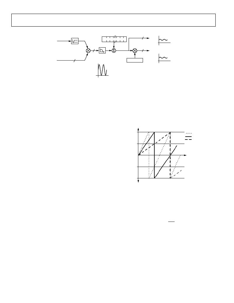
�Figure� 65.� Active� Power� Signal� Processing�
�02875-0-064�
�The� ADE7753� achieves� the� integration� of� the� active� power� signal� by�
�continuously� accumulating� the� active� power� signal� in� an� internal�
�nonreadable� 49-bit� energy� register.� The� active� energy� register�
�(AENERGY[23:0])� represents� the� upper� 24� bits� of� this� internal�
�register.� This� discrete� time� accumulation� or� summation� is�
�equivalent� to� integration� in� continuous� time.� Equation� 14�
�expresses� the� relationship.�
��(sinusoidal)� on� the� analog� inputs.� The� three� curves� displayed�
�illustrate� the� minimum� period� of� time� it� takes� the� energy� register�
�to� roll� over� when� the� active� power� gain� register� contents� are�
�0x7FF,� 0x000,� and� 0x800.� The� watt� gain� register� is� used� to� carry�
�out� power� calibration� in� the� ADE7753.� As� shown,� the� fastest�
�integration� time� occurs� when� the� watt� gain� register� is� set� to�
�E� =� ∫� p� (� t� )� dt� =� Lim� ?� ∑� p� (� nT� )� ×� T� ?�
�?� ∞� ?�
�t� →� 0� ?� n� =� 1� ?�
�(14)�
�maximum� full� scale,� i.e.,� 0x7FF.�
�AENERGY� [23:0]�
�where:�
�0x7F,FFFF�
�WGAIN� =� 0x7FF�
�WGAIN� =� 0x000�
�n� is� the� discrete� time� sample� number.�
�T� is� the� sample� period.�
�The� discrete� time� sample� period� (� T� )� for� the� accumulation�
�0x3F,FFFF�
�WGAIN� =� 0x800�
�register� in� the� ADE7753� is� 1.1μs� (4/CLKIN).� As� well� as�
�calculating� the� energy,� this� integration� removes� any� sinusoidal�
�0x00,0000�
�4� 6.2�
�8�
�12.5�
�TIME� (minutes)�
��shows� this� discrete� time� integration� or� accumulation.� The� active�
�power� signal� in� the� waveform� register� is� continuously� added� to�
�0x40,0000�
�the� internal� active� energy� register.� This� addition� is� a� signed�
�0x80,0000�
�02875-0-065�
�addition;� therefore� negative� energy� is� subtracted� from� the� active�
�energy� contents.� The� exception� to� this� is� when� POAM� is�
�selected� in� the� MODE[15:0]� register.� In� this� case,� only� positive�
�energy� contributes� to� the� active� energy� accumulation—see� the�
��The� output� of� the� multiplier� is� divided� by� WDIV.� If� the� value� in�
�the� WDIV� register� is� equal� to� 0,� then� the� internal� active� energy�
�register� is� divided� by� 1.� WDIV� is� an� 8-bit� unsigned� register.�
�After� dividing� by� WDIV,� the� active� energy� is� accumulated� in� a�
�49-bit� internal� energy� accumulation� register.� The� upper� 24� bits�
�of� this� register� are� accessible� through� a� read� to� the� active� energy�
�register� (AENERGY[23:0]).� A� read� to� the� RAENERGY� register�
�returns� the� content� of� the� AENERGY� register� and� the� upper� 24�
�bits� of� the� internal� register� are� cleared.� As� shown� in� Figure� 65,� the�
�active� power� signal� is� accumulated� in� an� internal� 49-bit� signed�
�register.� The� active� power� signal� can� be� read� from� the� waveform�
�register� by� setting� MODE[14:13]� =� 0,0� and� setting� the� WSMP�
�bit� (Bit� 3)� in� the� interrupt� enable� register� to� 1.� Like� the� Channel� 1�
�and� Channel� 2� waveform� sampling� modes,� the� waveform� date� is�
�available� at� sample� rates� of� 27.9� kSPS,� 14� kSPS,� 7� kSPS,� or�
��Figure� 66.� Energy� Register� Rollover� Time� for� Full-Scale� Power�
�(Minimum� and� Maximum� Power� Gain)�
�Note� that� the� energy� register� contents� rolls� over� to� full-scale�
�negative� (0x800000)� and� continues� to� increase� in� value� when�
�the� power� or� energy� flow� is� positive—see� Figure� 66.� Conversely,�
�if� the� power� is� negative,� the� energy� register� underflows� to� full-�
�scale� positive� (0x7FFFFF)� and� continues� to� decrease� in� value.�
�By� using� the� interrupt� enable� register,� the� ADE7753� can� be�
�configured� to� issue� an� interrupt� (IRQ)� when� the� active� energy�
�register� is� greater� than� half-full� (positive� or� negative)� or� when�
�an� overflow� or� underflow� occurs.�
�Integration� Time� under� Steady� Load�
�As� mentioned� in� the� last� section,� the� discrete� time� sample�
�period� (T)� for� the� accumulation� register� is� 1.1� μs� (4/CLKIN).�
�With� full-scale� sinusoidal� signals� on� the� analog� inputs� and� the�
�WGAIN� register� set� to� 0x000,� the� average� word� value� from� each�
�LPF2� is� 0xCCCCD—see� Figure� 61.� The� maximum� positive�
�value� that� can� be� stored� in� the� internal� 49-bit� register� is� 2� 48� or�
�Rev.� C� |� Page� 30� of� 60�
�相关PDF资料 |
PDF描述 |
|---|---|
| A7SSB-1506G | CABLE D-SUB-AFM15B/AE15G/AFM15B |
| HMM06DSUS | CONN EDGECARD 12POS .156 DIP SLD |
| GCC10DCAI-S189 | CONN EDGECARD 20POS R/A .100 SLD |
| ADE7759ARSZ | IC ENERGY METERING 1PHASE 20SSOP |
| RMM40DTAD-S189 | CONN EDGECARD 80POS R/A .156 SLD |
相关代理商/技术参数 |
参数描述 |
|---|---|
| ADE7753ARSZ | 制造商:Analog Devices 功能描述:ENERGY METERING IC |
| ADE7753ARSZ | 制造商:Analog Devices 功能描述:IC MULTIFUNCTION METER |
| ADE7753ARSZRL | 功能描述:IC ENERGY METERING 1PHASE 20SSOP RoHS:是 类别:集成电路 (IC) >> PMIC - 能量测量 系列:- 产品培训模块:Lead (SnPb) Finish for COTS Obsolescence Mitigation Program 标准包装:2,500 系列:* |
| ADE7753-ARSZRL | 制造商:Analog Devices 功能描述: |
| ADE7753XRS | 制造商:Analog Devices 功能描述: |
发布紧急采购,3分钟左右您将得到回复。