参数资料
| 型号: | DS2154LNA2+ |
| 厂商: | Maxim Integrated Products |
| 文件页数: | 49/124页 |
| 文件大小: | 0K |
| 描述: | IC TXRX E1 5V 100-LQFP |
| 产品培训模块: | Lead (SnPb) Finish for COTS Obsolescence Mitigation Program |
| 标准包装: | 90 |
| 类型: | 收发器 |
| 驱动器/接收器数: | 1/1 |
| 规程: | E1 |
| 电源电压: | 4.75 V ~ 5.25 V |
| 安装类型: | 表面贴装 |
| 封装/外壳: | 100-LQFP |
| 供应商设备封装: | 100-LQFP(14x14) |
| 包装: | 托盘 |
第1页第2页第3页第4页第5页第6页第7页第8页第9页第10页第11页第12页第13页第14页第15页第16页第17页第18页第19页第20页第21页第22页第23页第24页第25页第26页第27页第28页第29页第30页第31页第32页第33页第34页第35页第36页第37页第38页第39页第40页第41页第42页第43页第44页第45页第46页第47页第48页当前第49页第50页第51页第52页第53页第54页第55页第56页第57页第58页第59页第60页第61页第62页第63页第64页第65页第66页第67页第68页第69页第70页第71页第72页第73页第74页第75页第76页第77页第78页第79页第80页第81页第82页第83页第84页第85页第86页第87页第88页第89页第90页第91页第92页第93页第94页第95页第96页第97页第98页第99页第100页第101页第102页第103页第104页第105页第106页第107页第108页第109页第110页第111页第112页第113页第114页第115页第116页第117页第118页第119页第120页第121页第122页第123页第124页
DS21354/DS21554 3.3V/5V E1 Single-Chip Transceivers
30 of 124
5. CONTROL, ID, AND TEST REGISTERS
The operation of the DS21354/DS21554 is configured via a set of 10 control registers. Typically, the
control registers are only accessed when the system is first powered up. Once the device has been
initialized, the control registers need only to be accessed when there is a change in the system
configuration. There are two receive control registers (RCR1 and RCR2), two transmit control registers
(TCR1 and TCR2), and six common control registers (CCR1 to CCR6). Each of the 10 registers is
described in this section.
There is a device identification register (IDR) at address 0Fh. The MSB of this read-only register is fixed
to a one, indicating that an E1 SCT is present. The next three MSBs are used to indicate which E1 device
is present—DS2154, DS21354, or DS21554. The T1 pin-for-pin compatible SCTs have a logic zero in
the MSB position with the following three MSBs indicating which T1 SCT is present—DS2152,
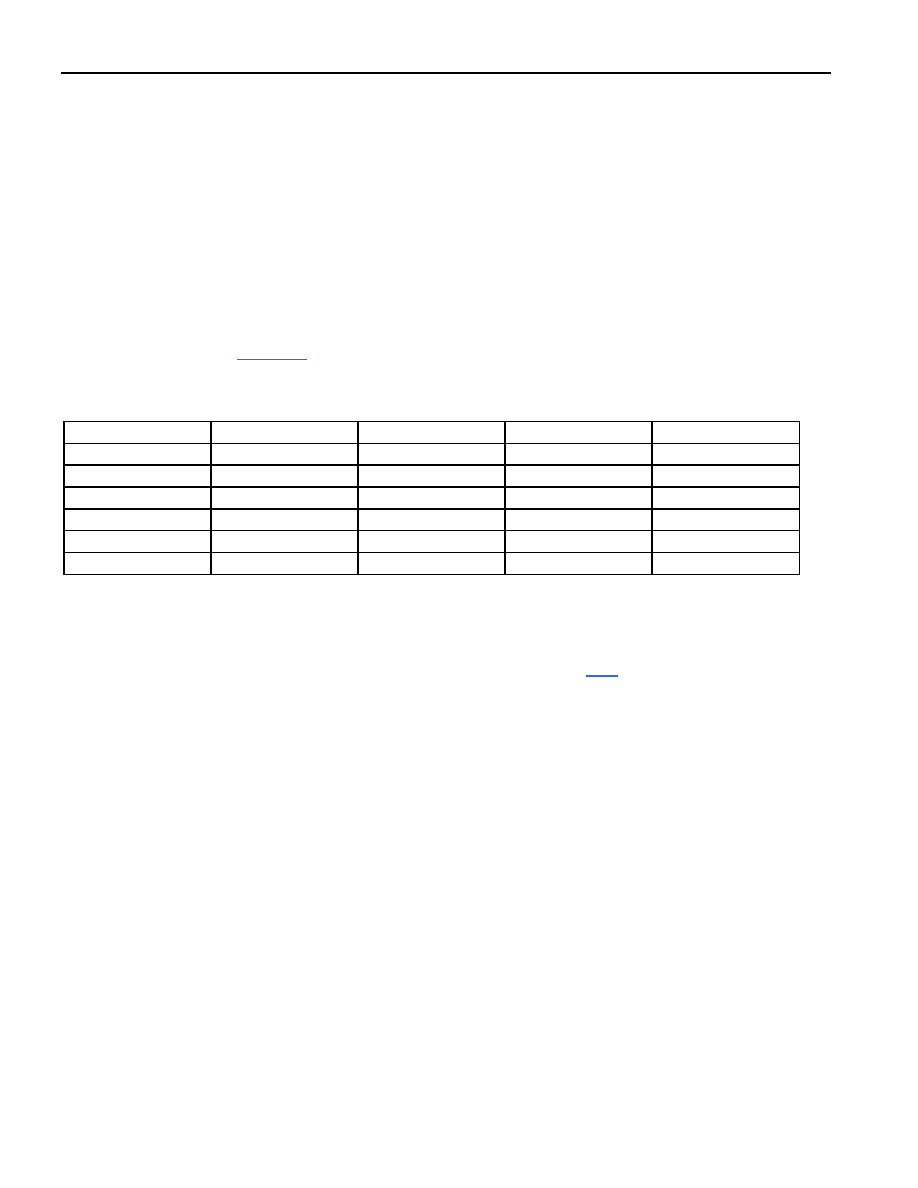
DS21352, or DS21552. Table 5-1 represents the possible variations of these bits and the associated SCT.
Table 5-1. Device ID Bit Map
SCT
T1/E1
BIT 6
BIT 5
BIT 4
DS2152
0
DS21352
0
1
DS21552
0
1
0
DS2154
1
0
DS21354
1
0
1
DS21554
1
0
1
0
The lower four bits of the IDR are used to display the die revision of the chip. The test registers at
addresses 09, 15, 19, and AC hex are used by the factory in testing the DS21354/DS21554. On power-up,
the test registers should be set to 00h in order for the DS21354/DS21554 to operate properly. Certain bits
of TEST3 are used to select monitor mode functions. Please see Section 15.5 for further details.
5.1.
Power-Up Sequence
On power-up, after the supplies are stable the DS21354/DS21554 should be configured for operation by
writing to all the internal registers (this includes setting the test registers to 00h) since the contents of the
internal registers cannot be predicted on power-up. The LIRST (CCR5.7) should be toggled from zero to
one to reset the line-interface circuitry (it will take the device about 40ms to recover from the LIRST bit
being toggled). Finally, after the TSYSCLK and RSYSCLK inputs are stable, the ESR bits (CCR6.0 and
CCR6.1) should be toggled from a zero to a one (this step can be skipped if the elastic stores are
disabled).
相关PDF资料 |
PDF描述 |
|---|---|
| DS2154L | IC TXRX E1 1CHIP 5V ENH 100-LQFP |
| DS2155LN | IC TXRX T1/E1/J1 1-CHIP 100-LQFP |
| DS2156LN+ | IC TXRX T1/E1/J1 1-CHIP 100-LQFP |
| DS2172T/T&R | IC TESTER BIT ERROR RATE 32-TQFP |
| DS2174QN+ | IC BERT ENHANCED 44-PLCC |
相关代理商/技术参数 |
参数描述 |
|---|---|
| DS2154LNA2+ | 功能描述:网络控制器与处理器 IC Enhanced E1 Transceiver RoHS:否 制造商:Micrel 产品:Controller Area Network (CAN) 收发器数量: 数据速率: 电源电流(最大值):595 mA 最大工作温度:+ 85 C 安装风格:SMD/SMT 封装 / 箱体:PBGA-400 封装:Tray |
| DS2154LND2 | 功能描述:网络控制器与处理器 IC RoHS:否 制造商:Micrel 产品:Controller Area Network (CAN) 收发器数量: 数据速率: 电源电流(最大值):595 mA 最大工作温度:+ 85 C 安装风格:SMD/SMT 封装 / 箱体:PBGA-400 封装:Tray |
| DS2154LND2+ | 制造商:Maxim Integrated Products 功能描述:ENHANCED E1 SCT LQFP REVD2 IND LF - Rail/Tube |
| DS2155 | 制造商:DALLAS 制造商全称:Dallas Semiconductor 功能描述:T1/E1/J1 Single-Chip Transceiver TDM/UTOPIA II Interface |
| DS2155_06 | 制造商:DALLAS 制造商全称:Dallas Semiconductor 功能描述:T1/E1/J1 Single-Chip Transceiver |
发布紧急采购,3分钟左右您将得到回复。