- 您现在的位置:买卖IC网 > PDF目录45186 > MB89PV950CF 8-BIT, 5 MHz, MICROCONTROLLER, CQFP64 PDF资料下载
参数资料
| 型号: | MB89PV950CF |
| 元件分类: | 微控制器/微处理器 |
| 英文描述: | 8-BIT, 5 MHz, MICROCONTROLLER, CQFP64 |
| 封装: | 0.80 MM PITCH, PIGGY BACK, MQFP-64 |
| 文件页数: | 57/110页 |
| 文件大小: | 619K |
| 代理商: | MB89PV950CF |
第1页第2页第3页第4页第5页第6页第7页第8页第9页第10页第11页第12页第13页第14页第15页第16页第17页第18页第19页第20页第21页第22页第23页第24页第25页第26页第27页第28页第29页第30页第31页第32页第33页第34页第35页第36页第37页第38页第39页第40页第41页第42页第43页第44页第45页第46页第47页第48页第49页第50页第51页第52页第53页第54页第55页第56页当前第57页第58页第59页第60页第61页第62页第63页第64页第65页第66页第67页第68页第69页第70页第71页第72页第73页第74页第75页第76页第77页第78页第79页第80页第81页第82页第83页第84页第85页第86页第87页第88页第89页第90页第91页第92页第93页第94页第95页第96页第97页第98页第99页第100页第101页第102页第103页第104页第105页第106页第107页第108页第109页第110页
HARDWARE CONFIGURATION
2– 35
(b) Pulse-width measurement function
a. Measurement start
Writing 1 at the EN bit (bit 7) and FC bit (bit 7) causes the counter to
enter the operation-enabled state. In this condition, counting starts when
the edge of the measured pulse input is detected. At the pulse-width
measurement function, counting down is started from FFH.
b. Measurement end and measured value
When measurement is terminated, the measured value is transferred to
the buffer, and the measurement-end flag IR (bit 1) and buffer-full flag
BF (bit 0) are set. causing the counter to re-enter the operation-enabled
state. At this time, an interrupt request is output when the IE bit (bit 5)
is set to 1. When the previous measured value cannot be read after
continuous pulse-width measurement, it is held by continuing to set the
BF flag. The new measured value is discarded.
c. Long pulse
When the counter underflows during measurement, the UF bit (bit 2) is
set to 1 to continue counting. In this case, an interrupt request is also
output when the IE bit (bit 5) is set to 1.
d. Measurement stop
Measurement stops when 0 is written at the EN bit (bit 7).
e. Calculation of pulse width
The count value when measurement is terminated is transferred as the
measured value to the buffer. Therefore, the pulse width should be
calculated using the following equation.
Pulse width = [(256 – count value) + (Number of TO counts inverted
×
256)]
× one cycle width of count clock pulse
f. Others
The counter remains in the operation-enabled state even after the end
of measurement, so continuous pulse-width measurement is possible.
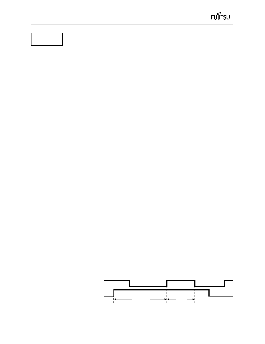
Measurement of a High pulse width is started from the changing edge
of the input pulse. If the EN bit is enabled (EN = 1) when the input pulse
is already High, counting is performed after the next rising edge.
Fig. 2.13 Measurement of High Pulse Width
Peripherals
Input pulse
EN signal
Count
Count stop
相关PDF资料 |
PDF描述 |
|---|---|
| MB89951PFM | 8-BIT, MROM, 5 MHz, MICROCONTROLLER, PQFP64 |
| MB89T623PFM | 8-BIT, 10 MHz, MICROCONTROLLER, PQFP64 |
| MB89623RP-SH | 8-BIT, MROM, 10 MHz, MICROCONTROLLER, PDIP64 |
| MB89625RPFV | 8-BIT, MROM, 10 MHz, MICROCONTROLLER, PQFP64 |
| MB89W627C-SH | 8-BIT, UVPROM, 10 MHz, MICROCONTROLLER, CDIP64 |
相关代理商/技术参数 |
参数描述 |
|---|---|
| MB89PV960 | 制造商:FUJITSU 制造商全称:Fujitsu Component Limited. 功能描述:8-bit Proprietary Microcontroller |
| MB89PV980-101 | 制造商:FUJITSU 制造商全称:Fujitsu Component Limited. 功能描述:8-bit Proprietary Microcontroller |
| MB89PV980-201 | 制造商:FUJITSU 制造商全称:Fujitsu Component Limited. 功能描述:8-bit Proprietary Microcontroller |
| MB89PW625 | 制造商:FUJITSU 制造商全称:Fujitsu Component Limited. 功能描述:8-bit Proprietary Microcontroller |
| MB89R112B1QN-G-AMERE1 | 制造商:FUJITSU 功能描述: |
发布紧急采购,3分钟左右您将得到回复。