- 您现在的位置:买卖IC网 > PDF目录371012 > MC144144P (MOTOROLA INC) Digital Signal Processors 44-JLCC -55 to 125 PDF资料下载
参数资料
| 型号: | MC144144P |
| 厂商: | MOTOROLA INC |
| 元件分类: | 颜色信号转换 |
| 英文描述: | Digital Signal Processors 44-JLCC -55 to 125 |
| 中文描述: | COLOR SIGNAL DECODER, PDIP18 |
| 封装: | PLASTIC, DIP-18 |
| 文件页数: | 16/44页 |
| 文件大小: | 565K |
| 代理商: | MC144144P |
第1页第2页第3页第4页第5页第6页第7页第8页第9页第10页第11页第12页第13页第14页第15页当前第16页第17页第18页第19页第20页第21页第22页第23页第24页第25页第26页第27页第28页第29页第30页第31页第32页第33页第34页第35页第36页第37页第38页第39页第40页第41页第42页第43页第44页
MC144144
16
MOTOROLA
master device must generate the clock for the acknowledge
bit. Acknowledge is SDA = LOW.
Data
– The data (SDA) is output by the transmitting device
on the falling edge of SCK, MSB first. The receiving device
will read the data, MSB first on the rising edge of SCK.
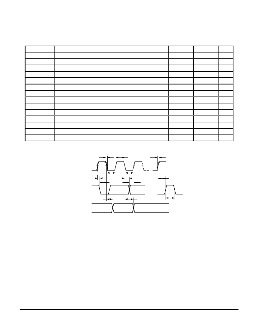
TWO WIRE SERIAL MODE REQUIREMENTS
ááááááááááááááááááááááááááááááá
ááááááááááááááááááááááááááááááá
ááááááááááááááááááááááááááááááá
ááááááááááááááááááááááá
ááááááááááááááááááááááááááááááá
ááááááááááááááááááááááááááááááá
ááááááááááááááááááááááááááááááá
ááááááááááááááááááááááááááááááá
ááááááááááááááááááááááááááááááá
ááááááááááááááááááááááááááááááá
ááááááááááááááááááááááááááááááá
ááááááááááááááááááááááááááááááá
Symbol
Parameter
Min
Max
Unit
Clock Frequency
ááááááááááááááááááááááááááááááá
Clock Pulse Width Low
Clock Pulse Width High
SDA and SCL Rise Time
SDA and SCL Fall Time
Clock Low to Data Out Valid
Bus Free Time
Start Hold Time
Start Setup Time
Data In Hold Time
Data In Setup Time
Stop Setup Time
Data Out Hold Time
Input Filter TC
—
4.7
4.0
—
—
0.1
4.7
4.0
4.7
0
250
4.7
100
—
100
—
—
1.0
300
3.5
—
—
—
—
—
—
—
100
kHz
μ
s
μ
s
s
ns
μ
s
s
μ
s
μ
s
μ
s
ns
s
ns
ns
ááááááááááááááááááááááááááááááá
ááááááááááááááááááááááááááááááá
ááááááááááááááááááááááááááááááá
SCK
tHIGH
tLOW
tHDDAT
tSUDAT
tLOW
tf
tSUSTA
tHDSTA
tBUF
tSUSTO
tr
tAA
tDH
SDA IN
SDA OUT
Figure 6. Two–Wire Serial Mode
Communication with the MC144144 is initiated when the
master device sends the MC144144 slave address following
the start condition. The MC144144 has a preset, single,
seven–bit slave address. The MC144144 will respond with
an acknowledge. The eighth bit of the slave address is driven
high for read operations and low for write operations.
Writing to the I2C Bus
All write commands are either one or two byte commands.
The number of data bytes to be received by the MC144144 is
inherent in the command and the MC144144 will respond
with the acknowledge signal only for the number of bytes ex-
pected. If the master writes more bytes than expected, there
will be no acknowledge for the extra bytes.
The MC144144 is enabled when a start condition followed
by its slave address byte is received. It will be disabled once
it deems the command to have been completed or by a stop
condition. A new start condition without a stop condition will
begin a new sequence. Therefore, successive commands
may be executed by successive strings of “start – slave ad-
dress – command” sequences without any intervening stop
condition being sent.
A write to the MC144144 should always be preceded by
executing a status read to verify that the MC144144 is not
busy. The status register data is output immediately following
the reception of the slave address with the read bit set. If the
RDY bit is set, the master device can initiate its write se-
quence, always beginning with the start condition. The first
byte of a two byte command is written first.
相关PDF资料 |
PDF描述 |
|---|---|
| MC14415DW | Digital Signal Processors 40-CDIP SB -55 to 125 |
| MC14415FL | Quad Precision Timer/Driver |
| MC14415FP | Quad Precision Timer/Driver |
| MC14415VL | Digital Signal Processors 68-CPGA -55 to 125 |
| MC14415VP | Digital Signal Processors 68-LCCC -55 to 125 |
相关代理商/技术参数 |
参数描述 |
|---|---|
| MC14415FP | 制造商:Motorola Inc 功能描述: |
| MC14416P | 制造商:Motorola Inc 功能描述: 制造商:Motorola Inc 功能描述:TIME-SLOT ASSIGNER, 22 Pin, Plastic, DIP |
| MC14419P | 制造商:Motorola Inc 功能描述:ENCODER, 16 Pin, Plastic, DIP |
| MC14433P | 制造商:Motorola Inc 功能描述: |
| MC1443G | 制造商:Motorola Inc 功能描述: |
发布紧急采购,3分钟左右您将得到回复。