- 您现在的位置:买卖IC网 > PDF目录371012 > MC144144P (MOTOROLA INC) Digital Signal Processors 44-JLCC -55 to 125 PDF资料下载
参数资料
| 型号: | MC144144P |
| 厂商: | MOTOROLA INC |
| 元件分类: | 颜色信号转换 |
| 英文描述: | Digital Signal Processors 44-JLCC -55 to 125 |
| 中文描述: | COLOR SIGNAL DECODER, PDIP18 |
| 封装: | PLASTIC, DIP-18 |
| 文件页数: | 20/44页 |
| 文件大小: | 565K |
| 代理商: | MC144144P |
第1页第2页第3页第4页第5页第6页第7页第8页第9页第10页第11页第12页第13页第14页第15页第16页第17页第18页第19页当前第20页第21页第22页第23页第24页第25页第26页第27页第28页第29页第30页第31页第32页第33页第34页第35页第36页第37页第38页第39页第40页第41页第42页第43页第44页
MC144144
20
MOTOROLA
NOTE: For XDS data recovery, when the XDS filter regis-
ter (see
Internal Register
section) is enabled for the desired
packets, the internal program will automatically establish the
two byte recovery mode and move the recovered data bytes
to the output register.
Reads
READ1 = F8h —
Command to read one byte in the SPI
mode.
READ2 = F9h —
Command to read two bytes in the SPI
mode.
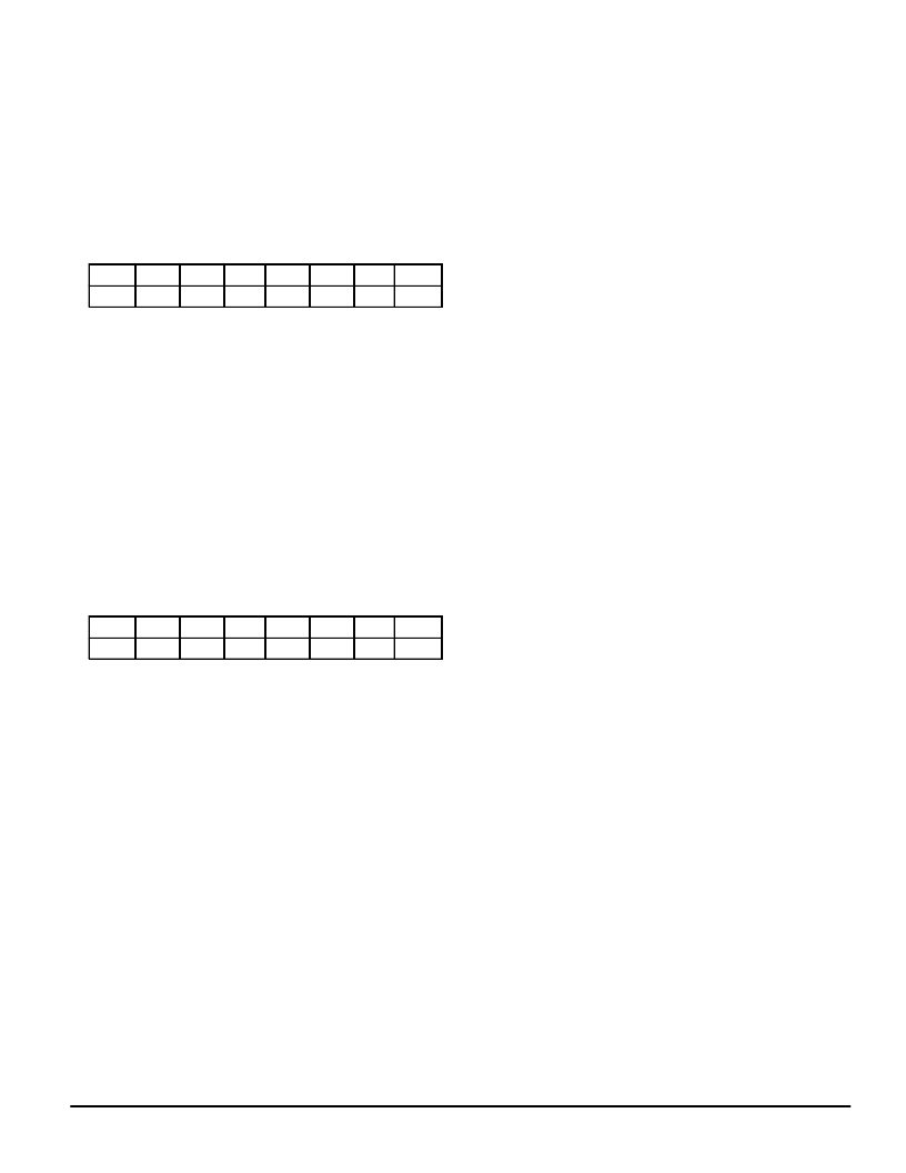
CM7
CM6
CM5
CM4
CM3
CM2
CM1
CM0
1
1
1
1
1
0
0
RD2
The READx commands do not affect the status of the RDY
bit in the serial status (SS) register and can be executed in-
dependent of the RDY status.
In both serial communications modes, the DAV bit in the
SS register indicates when data is available. When the RD2
bit is LOW, DAV is cleared on the rising edge of SCK at the
LSB of the first data byte. When the RD2 bit is HIGH, DAV is
cleared on the rising edge of SCK at the LSB of the second
data byte. The RD2 bit is only valid if DAV is HIGH.
Reading in the I2C mode is selected by the R/NW bit in the
slave address byte. The first byte after the slave address
byte will be SS followed by the data in output buffers A and B.
If the instruction being executed is a one byte read, then the
contents of buffer B will be all ones.
Write
WRx = C0h–DFh
CM7
CM6
CM5
CM4
CM3
CM2
CM1
CM0
1
1
0
AD4
AD3
AD2
AD1
AD0
The WRITE commands require two bytes to execute. The
first byte is the write command and includes the address be-
ing written to. The second byte will be the data byte.
OSD DISPLAY MODE COMMANDS
OSD commands are one and two byte commands. They
are used to control the loading of data for OSD display and
their presentation to the screen. Normally OSD display mode
uses 15 TV lines per display row to enhance the screen ap-
pearance.
The one–byte commands are:
CMD
Byte
Function
30h
(RETURN)
Carriage return for OSD when in
TEXTSET mode.
31h
(CLRE)
OSD equivalent to delete to end
of row (DER).
32h
(TEXTSET)
Establishes a text type of OSD
display.
33h
(POPSET)
Establishes a pop–on type of
OSD display.
36h
(FLIP)
OSD equivalent of pop–on cap-
tion end of caption (EOC).
37h
(OEDM)
OSD equivalent to erase dis-
played memory.
38h
(OENM)
OSD equivalent to erase non–dis-
played memory.
The two–byte commands are:
A0h rr
POP ROW SEL
Sets display row and moves cur-
sor to char column 1. The low or-
der nibble of rr designates the
display row. Bit 5 of rr specifies a
double high row. For example:
rr = 0Eh would select display row
14. rr = 23h would select display
row three, double high.
Sets the physical row, where the
low order nibble of rr designates
the physical row. rr can be any
value from 00h to 0Fh.
Places the cursor at the character
position designated by cc, which
can be any value from 00h to 20h
(column 0 – 32). Zero is the PAC
space.
Writes the data byte dd to the cur-
rent cursor location and then in-
crements the cursor.
Maps the current physical row to
the display row designated by the
low nibble of the rr byte. Bit 4 of
rr = 1 enables display of the row.
Bit 5 of rr = 1 indicates a double
high row.
Same as A3 command but speci-
fies a double wide character.
Sets the RDY bit of SS and then
suspends serial command execu-
tion for approximately the number
of frames designated by the nn
byte.
A1h rr
PHY ROW SEL
A2h cc
CURSOR SET
A3h dd
WRITE CHAR
A4h rr
WRITE MAP
A5h dd
WRITE CHARD
A6h nn
WAIT
Figure 9 shows the two different character sets, graphics
or extended, that share the address space C0h – FFh. The
graphics character set is in force when the OSD display is in
drop shadow mode (the default condition). The following two
byte commands can be used to switch from the graphics
characters to the extended characters and vice versa. An
OSD screen can only use one set at a time.
84h 30h GRAPHICS
Sets the graphics character set in
force.
8Ch 30h EXTENDED
Sets the extended character set
in force.
相关PDF资料 |
PDF描述 |
|---|---|
| MC14415DW | Digital Signal Processors 40-CDIP SB -55 to 125 |
| MC14415FL | Quad Precision Timer/Driver |
| MC14415FP | Quad Precision Timer/Driver |
| MC14415VL | Digital Signal Processors 68-CPGA -55 to 125 |
| MC14415VP | Digital Signal Processors 68-LCCC -55 to 125 |
相关代理商/技术参数 |
参数描述 |
|---|---|
| MC14415FP | 制造商:Motorola Inc 功能描述: |
| MC14416P | 制造商:Motorola Inc 功能描述: 制造商:Motorola Inc 功能描述:TIME-SLOT ASSIGNER, 22 Pin, Plastic, DIP |
| MC14419P | 制造商:Motorola Inc 功能描述:ENCODER, 16 Pin, Plastic, DIP |
| MC14433P | 制造商:Motorola Inc 功能描述: |
| MC1443G | 制造商:Motorola Inc 功能描述: |
发布紧急采购,3分钟左右您将得到回复。