- 您现在的位置:买卖IC网 > PDF目录371012 > MC144144P (MOTOROLA INC) Digital Signal Processors 44-JLCC -55 to 125 PDF资料下载
参数资料
| 型号: | MC144144P |
| 厂商: | MOTOROLA INC |
| 元件分类: | 颜色信号转换 |
| 英文描述: | Digital Signal Processors 44-JLCC -55 to 125 |
| 中文描述: | COLOR SIGNAL DECODER, PDIP18 |
| 封装: | PLASTIC, DIP-18 |
| 文件页数: | 21/44页 |
| 文件大小: | 565K |
| 代理商: | MC144144P |
第1页第2页第3页第4页第5页第6页第7页第8页第9页第10页第11页第12页第13页第14页第15页第16页第17页第18页第19页第20页当前第21页第22页第23页第24页第25页第26页第27页第28页第29页第30页第31页第32页第33页第34页第35页第36页第37页第38页第39页第40页第41页第42页第43页第44页
MC144144
21
MOTOROLA
INTERNAL REGISTERS
Information controlling the setup and operation of the
MC144144 are maintained in several registers. The user
may read or alter the contents of these registers as required.
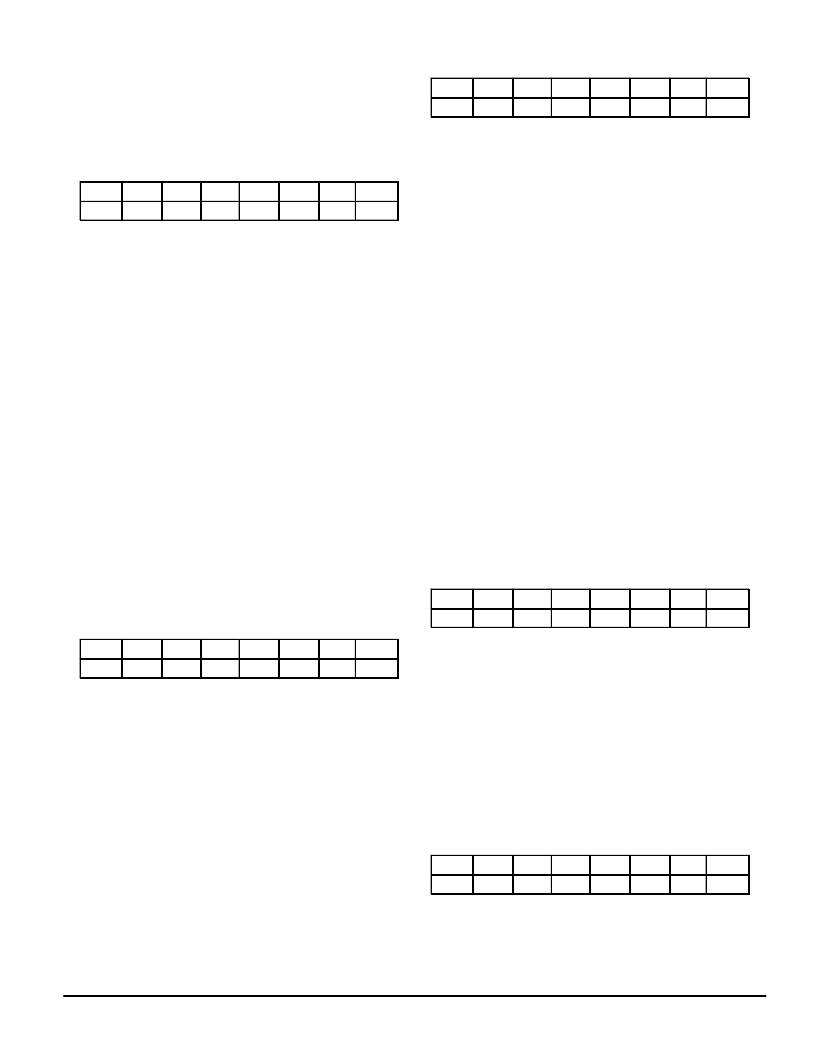
Serial Status (SS) Register —
Address = Not Required
(see
Serial Communications Interface
section)
D7
D6
D5
D4
D3
D2
D1
D0
RDY
DAV
RD2
WOVR
INTR
ROVR
FLD
LOCK
D7 – RDY —
Active HIGH, indicating that the port input buff-
er is empty. Only the NOP, RESET, and READ instructions
may be sent if RDY is LOW.
D6 – DAV —
Active HIGH, indicating that data is available to
be read out.
D5 – RD2 —
Signals the number of bytes available for out-
put. LOW = 1 byte, HIGH = 2 bytes.
D4 – WOVR —
Active HIGH, indicating a serial input data
overrun.
D3 – INTR —
Active HIGH, indicating that an interrupt other
than DAV is pending.
D2 – ROVR —
Active HIGH, indicating that the data avail-
able in the output buffer has not been read out and new data
has been written over it.
D1 – FLD —
Signals the current video field. LOW = Field 2,
HIGH = Field 1.
D0 – LOCK —
Active HIGH, indicating that the internal sync
circuits are locked. Maybe used as an indication of the pres-
ence of a video signal.
Configuration Register —
Address = 00h
D7
D6
D5
D4
D3
D2
D1
D0
res
res
res
res
VLK
HLK
MONO
TVS
D0 – TVS —
Selects the television standard. HIGH selects
PAL and LOW selects NTSC. The default is NTSC. When
PAL is selected the display defaults to 15 TV lines per display
row.
D1 – MONO —
Selects monochrome operation. Active
HIGH, indicating that character luminance will be output on
the color pins. Default is LOW, selecting COLOR operation.
D2 – HLK —
Selects the horizontal signal source to be used
to lock the VCO. LOW = internal, HIGH = HIN. The default is
internal.
D3 – VLK —
Selects the vertical signal source to be used to
establish vertical sync lock. LOW = internal, HIGH = VIN.
The default is internal. When internal lock is enabled the VIN/
INTRO pin will default to the INTRO output mode. Interrupts
should not be selected in the interrupt mask register if VLK
mode is used.
D4 – D7 —
Reserved
Display Register —
Address = 01h
D7
D6
D5
D4
D3
D2
D1
D0
O15
ODRP
CENH
C15
CDRP
TENH
T15
TDRP
D0 – TDRP —
Selects drop shadow or full box in TEXT
mode. HIGH = DROP SHADOW and LOW = BOX. The de-
fault is LOW.
D1 – T15 —
Selects the number of TV lines per character
row in a TEXT display. HIGH = 15 lines/row and LOW = 13
lines/row. The default is LOW.
D2 – TENH —
Enables enhanced attributes for a TEXT dis-
play. HIGH = disabled, LOW = enabled. The default is LOW.
D3 – CDRP —
Selects drop shadow or full box in CAPTION
mode. High = DROP SHADOW and LOW = BOX. The de-
fault is LOW.
D4 – C15 —
Selects the number of TV lines per character
row in a CAPTION display. HIGH = 15 lines/row and LOW =
13 lines/row. The default is LOW.
D5 – CENH —
Enables enhanced attributes for a CAPTION
display. HIGH = disabled, LOW = enabled. The default is
LOW.
D6 – ODRP —
Selects drop shadow or full box in the OSD
and XDS display modes. High = DROP SHADOW and LOW
= BOX. The default is HIGH.
D7 – O15 —
Selects the number of TV lines per character
row in the OSD and XDS display modes. HIGH = 15 lines/
row and LOW = 13 lines/row. The default is HIGH.
NOTE: OSD and XDS display modes always have en-
hanced attributes enabled.
H Position Register —
Address = 02h
D7
D6
D5
D4
D3
D2
D1
D0
BLBX
HPOL
h5
h4
h3
h2
h1
h0
D0 – D5 = h0 – h5
Used to set the horizontal timing of the display. The default
value in this register is 26h. Each count change represents a
timing change of 330 ns. Lower numbers move the display to
the RIGHT. Conversely, larger numbers move the display to
the LEFT.
D6 – HPOL —
Set the polarity to be used for locking to the
HIN signal when in the EXT HLK mode. LOW = rising edge,
HIGH = falling edge. The default is LOW.
D7 – BLBX —
Designates color of BOX. HIGH = blue box
and LOW = black box. The default is LOW.
Text Position Register —
Address = 03h
D7
D6
D5
D4
D3
D2
D1
D0
y3
y2
y1
y0
x3
x2
x1
x0
D0 – D3 = x0 – x3
Sets the number of rows in the TEXT display. The default is
15 rows.
D4 – D7 = y0 – y3
Sets the base row of the TEXT display.
相关PDF资料 |
PDF描述 |
|---|---|
| MC14415DW | Digital Signal Processors 40-CDIP SB -55 to 125 |
| MC14415FL | Quad Precision Timer/Driver |
| MC14415FP | Quad Precision Timer/Driver |
| MC14415VL | Digital Signal Processors 68-CPGA -55 to 125 |
| MC14415VP | Digital Signal Processors 68-LCCC -55 to 125 |
相关代理商/技术参数 |
参数描述 |
|---|---|
| MC14415FP | 制造商:Motorola Inc 功能描述: |
| MC14416P | 制造商:Motorola Inc 功能描述: 制造商:Motorola Inc 功能描述:TIME-SLOT ASSIGNER, 22 Pin, Plastic, DIP |
| MC14419P | 制造商:Motorola Inc 功能描述:ENCODER, 16 Pin, Plastic, DIP |
| MC14433P | 制造商:Motorola Inc 功能描述: |
| MC1443G | 制造商:Motorola Inc 功能描述: |
发布紧急采购,3分钟左右您将得到回复。