参数资料
| 型号: | NCN6000DTBR2G |
| 厂商: | ON Semiconductor |
| 文件页数: | 36/36页 |
| 文件大小: | 0K |
| 描述: | IC INTERFACE SMART CARD 20TSSOP |
| 产品变化通告: | Product Obsolescence 01/Jul/2009 |
| 标准包装: | 1 |
| 应用: | ATM 终端,气泵,ISM |
| 接口: | 微控制器 |
| 电源电压: | 2.7 V ~ 6 V |
| 封装/外壳: | 20-TSSOP(0.173",4.40mm 宽) |
| 供应商设备封装: | 20-TSSOP |
| 包装: | 剪切带 (CT) |
| 安装类型: | 表面贴装 |
| 其它名称: | NCN6000DTBR2GOSCT |
第1页第2页第3页第4页第5页第6页第7页第8页第9页第10页第11页第12页第13页第14页第15页第16页第17页第18页第19页第20页第21页第22页第23页第24页第25页第26页第27页第28页第29页第30页第31页第32页第33页第34页第35页当前第36页
NCN6000
http://onsemi.com
9
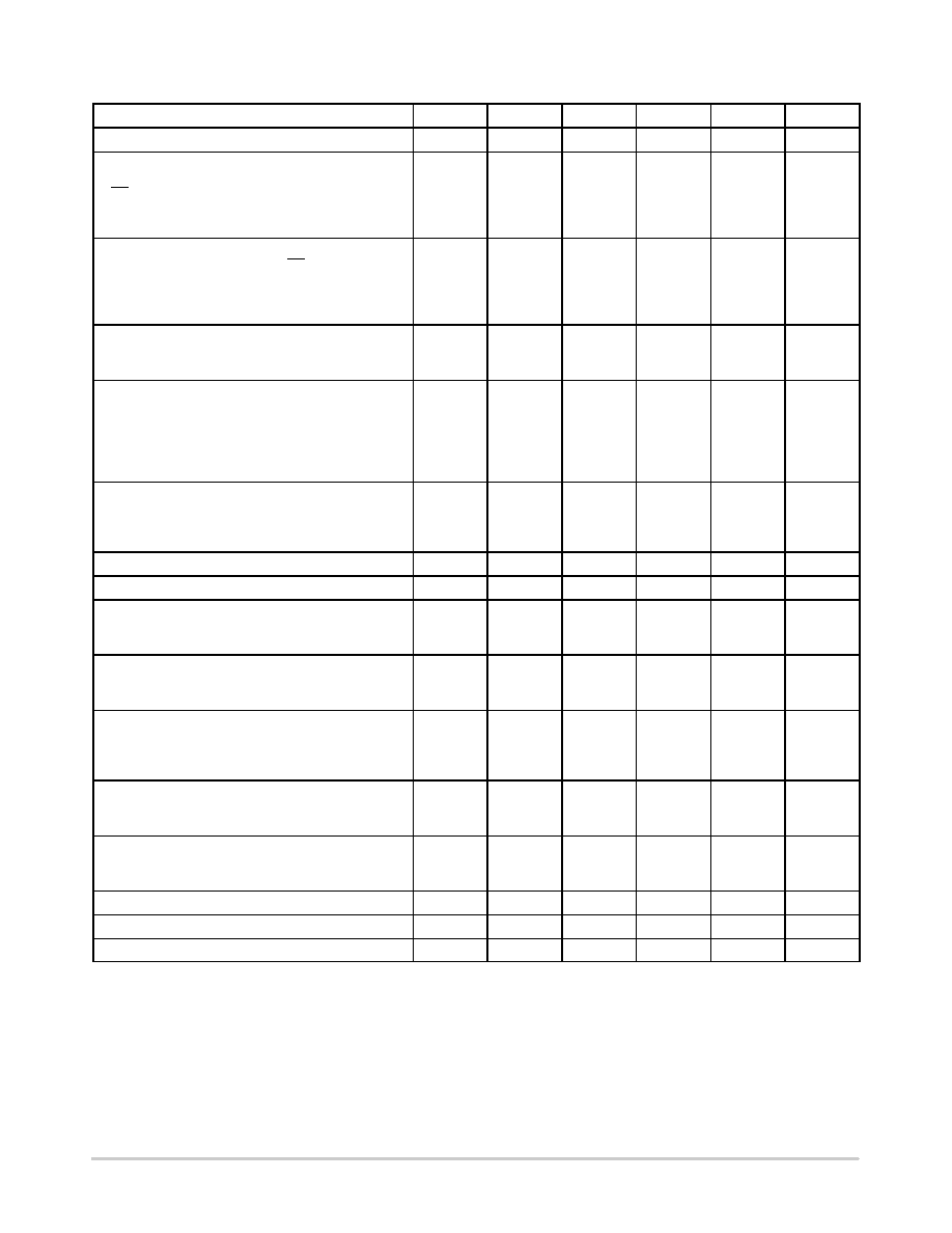
POWER SUPPLY SECTION (25
°C to +85°C ambient temperature, unless otherwise noted.)
Rating
Symbol
Pin
Min
Typ
Max
Unit
Power Supply
Vbat
20
2.7
6.0
V
Standby Supply Current Conditions:
PWR_ON = L, STATUS = H, CLOCK_IN = H,
CS = H. All other logic inputs and outputs are open:
Vbat = 3.0 V
Vbat = 5.0 V
Ibatsb
20
3.0
8.0
15
mA
DC Operating Current (Figure 19)
PWR_ON = H, CLOCK_IN = 0, CS = H, all CRD pins
unloaded
@ Vbat = 6.0 V, CRD_VCC = 5.0 V
@ Vbat = 3.6 V, CRD_VCC = 5.0 V
Ibatop
20
7.0
2.0
5.0
mA
Vbat Undervoltage DetectionHigh
Vbat Undervoltage DetectionLow
Vbat Undervoltage DetectionHysteresis
VbatLH
VbatLL
VbatHY
20
2.1
2.0
100
2.7
2.6
V
mV
Output Card Supply Voltage @ Icc = 55 mA
@ 2.70 V
vVbat v6.0 V
CRD_VCC = 3.0 V
CRD_VCC = 5.0 V
@ VbatLL < Vbat < 2.70 V
CRD_VCC = 5.0 V
Vcc
VC3H
VC5H
15
2.75
4.75
4.50
3.25
5.25
V
Output Card Supply Peak Current @ Vcc = 5.0 V
@ CRD_VCC = 5.0 V
@ CRD_VCC = 3.0 V
@ Vbat = 3.6 V, CRD_VCC = 5.0 V, Tamb < 65
°C
Iccp
15
55
65
mA
Output Current Limit Time Out
tdoff
15
4.0
ms
Output Over Current Limit
Iccov
15
100
mA
Output Dynamic Peak Current @ CRD_VCC = 3.0 V
or 5.0 V, Cout = 10
mF Ceramic XR7, Pulse Width
Iccd
15
100
mA
Battery StartUp Current
@ CRD_VCC = 3.0 V, 25
°C v TA v+ 85°C
@ CRD_VCC = 5.0 V, 25
°CvTAv+ 85°C
Iccst
20
140
300
mA
Output Card Supply Voltage Ripple @ Lout = 22
mH,
Cout 1 = 10
mF, Cout 2 = 100 nF, Vbat = 3.6 V
Iout = 55 mA
CRD_VCC = 5.0 V
(Note 5)
CRD_VCC = 3.0V
Vccrip
15
50
mV
Output Card Supply Turn On Time @ Lout = 22
mF,
Cout1 = 10
mF, Cout2 = 100 nF, Vbat = 2.7 V,
CRD_VCC = 5.0 V
VccTON
15
2.0
ms
Output Card Supply Shut Off Time @ Cout1 = 10
mF,
Ceramic, Vbat = 2.7 V, CRD_VCC = 5.0 V,
VccOFF < 0.4 V
VccTOFF
15
250
ms
DCDC Converter Operating Frequency
Fsw
18
600
kHz
Power Switch Drain/Source Resistor
RONS
18
1.9
2.2
W
Output Rectifier ON Resistor
ROND
15
2.8
3.4
W
5. Ceramic X7R, SMD types capacitors are mandatory to achieve the CRD_VCC specifications. When electrolytic capacitor is used, the
external filter must include a 100 nF, max 50 m
W ESR capacitor in parallel, to reduce both the high frequency noise and ripple to a minimum.
Depending upon the PCB layout, it might be necessary is to use two 6.8
mF/10 V/ceramic/X7R//SMD1206 in parallel, yielding an improved
CRD_VCC ripple over the temperature range.
6. According to ISO78163, paragraph 4.3.2.
相关PDF资料 |
PDF描述 |
|---|---|
| NCN6001DTBR2 | IC INTERFACE SMART CARD 20TSSOP |
| NCN6004AFTBR2G | IC INTERFACE SAM/SIM DUAL 48TQFP |
| NCN6804MNR2G | IC SMART CARD DUAL W/SPI 32-QFN |
| NCN7200MTTWG | IC MUX/DEMUX OCTAL 1X2 42WQFN |
| NCN8024DTBR2G | SMART CARD IC 5V/3V TSSOP |
相关代理商/技术参数 |
参数描述 |
|---|---|
| NCN6001 | 制造商:ONSEMI 制造商全称:ON Semiconductor 功能描述:Smartcard Interface ICs |
| NCN6001/D | 制造商:ONSEMI 制造商全称:ON Semiconductor 功能描述:Compact Smart Card Interface IC |
| NCN6001_06 | 制造商:ONSEMI 制造商全称:ON Semiconductor 功能描述:Compact Smart Card Interface IC |
| NCN6001_0610 | 制造商:ONSEMI 制造商全称:ON Semiconductor 功能描述:Smartcard Interface ICs |
| NCN6001DTBEVB | 功能描述:界面开发工具 NCN6001 TSSOP EVAL BOARD RoHS:否 制造商:Bourns 产品:Evaluation Boards 类型:RS-485 工具用于评估:ADM3485E 接口类型:RS-485 工作电源电压:3.3 V |
发布紧急采购,3分钟左右您将得到回复。