参数资料
| 型号: | NCN6000DTBR2G |
| 厂商: | ON Semiconductor |
| 文件页数: | 8/36页 |
| 文件大小: | 0K |
| 描述: | IC INTERFACE SMART CARD 20TSSOP |
| 产品变化通告: | Product Obsolescence 01/Jul/2009 |
| 标准包装: | 1 |
| 应用: | ATM 终端,气泵,ISM |
| 接口: | 微控制器 |
| 电源电压: | 2.7 V ~ 6 V |
| 封装/外壳: | 20-TSSOP(0.173",4.40mm 宽) |
| 供应商设备封装: | 20-TSSOP |
| 包装: | 剪切带 (CT) |
| 安装类型: | 表面贴装 |
| 其它名称: | NCN6000DTBR2GOSCT |
第1页第2页第3页第4页第5页第6页第7页当前第8页第9页第10页第11页第12页第13页第14页第15页第16页第17页第18页第19页第20页第21页第22页第23页第24页第25页第26页第27页第28页第29页第30页第31页第32页第33页第34页第35页第36页
NCN6000
http://onsemi.com
16
Programming Mode
The programming mode allows the configuration of the
card power supply, card clock and Card Detection input
logic polarity. These signals (CRD_VCC, CRD_CLK and
CRD_DET) are described in the pin description paragraph
Programming Mode
Logic Conditions:
Card Output:
CS
= L
PWR_ON = L
A0
= H/L
A1
= H/L
PGM
= L
I/O
= L/H
RESET
= L/H
CRD_VCC = 0 V
CRD_CLK = L
CRD_RST = L
CRD_IO
= H/L depending upon
the previous I/O pin
logic state
The I/O and RESET pins are not connected to the smart
card and become logic inputs to control the NCN6000
programming sequence. The programmed values are
latched upon transition of CS from Low to High, PGM being
Low during the transition.
When a programming mode is validated by a Chip Select
negative going transient, the mode is latched and PGM can
be released to High. This latch is automatically reset when
CS returns to High.
The logic input signals can be set simultaneously, or one
bit a time (using either a STAA or a BSET function), the key
point being the minimum delay between the shorter bit and
the Chip Select pulse. The programmed value is latched into
the NCN6000 register on the CS positive going edge.
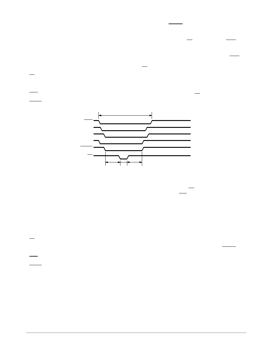
PROGRAMMING
2
ms2 ms
1
ms
NORMAL MODE
PGM
I/O
A0
A1
RESET
CS
Figure 8. Minimum Programming Timings
Active Mode
In the active mode, the NCN6000 is selected by the
external MPU and the STATUS pin can be polled to get the
status of either the DCDC converter or the presence of the
card (inserted or not valid). The power is not connected to
the card: CRD_VCC = 0 V.
Active Mode
Logic Conditions:
Card Output:
CS
= L
PWR_ON = L
A0
= L
A1
= L
PGM
= H
I/O
= Z
RESET
= Z
STATUS
= L/H is Card
Inserted?
CRD_VCC = 0 V
CRD_CLK = L
CRD_RST = L
CRD_IO
= H/L depending upon
the previous I/O pin
logic state
The Chip Select pulse [CS] will automatically clear the
previously asserted INT signal upon the positive going
transition.
If a card is present, the MPU shall activate the DCDC
converter by asserting PWR_ON = H. The NCN6000 will
automatically run a power up sequence when the
CRD_VCC reaches the undervoltage level (either VC5H or
VC3H, depending upon the CRD_VCC voltage supply
programmed). The CRD_IO, CRD_RST and CRD_CLK
pins are validated, according to the ISO78163 sequence.
The interface is now in transaction mode and the system is
ready for data exchange through the I/O and RESET lines.
At any time, the microcontroller can change the CRD_CLK
frequency and mode, or the CRD_VCC value as determined
by the card being in use.
相关PDF资料 |
PDF描述 |
|---|---|
| NCN6001DTBR2 | IC INTERFACE SMART CARD 20TSSOP |
| NCN6004AFTBR2G | IC INTERFACE SAM/SIM DUAL 48TQFP |
| NCN6804MNR2G | IC SMART CARD DUAL W/SPI 32-QFN |
| NCN7200MTTWG | IC MUX/DEMUX OCTAL 1X2 42WQFN |
| NCN8024DTBR2G | SMART CARD IC 5V/3V TSSOP |
相关代理商/技术参数 |
参数描述 |
|---|---|
| NCN6001 | 制造商:ONSEMI 制造商全称:ON Semiconductor 功能描述:Smartcard Interface ICs |
| NCN6001/D | 制造商:ONSEMI 制造商全称:ON Semiconductor 功能描述:Compact Smart Card Interface IC |
| NCN6001_06 | 制造商:ONSEMI 制造商全称:ON Semiconductor 功能描述:Compact Smart Card Interface IC |
| NCN6001_0610 | 制造商:ONSEMI 制造商全称:ON Semiconductor 功能描述:Smartcard Interface ICs |
| NCN6001DTBEVB | 功能描述:界面开发工具 NCN6001 TSSOP EVAL BOARD RoHS:否 制造商:Bourns 产品:Evaluation Boards 类型:RS-485 工具用于评估:ADM3485E 接口类型:RS-485 工作电源电压:3.3 V |
发布紧急采购,3分钟左右您将得到回复。