- 您现在的位置:买卖IC网 > PDF目录370133 > 7549 (Renesas Technology Corp.) SINGLE-CHIP 8-BIT CMOS MICROCOMPUTER PDF资料下载
参数资料
| 型号: | 7549 |
| 厂商: | Renesas Technology Corp. |
| 英文描述: | SINGLE-CHIP 8-BIT CMOS MICROCOMPUTER |
| 中文描述: | 单芯片8位CMOS微机 |
| 文件页数: | 10/73页 |
| 文件大小: | 1272K |
| 代理商: | 7549 |
第1页第2页第3页第4页第5页第6页第7页第8页第9页当前第10页第11页第12页第13页第14页第15页第16页第17页第18页第19页第20页第21页第22页第23页第24页第25页第26页第27页第28页第29页第30页第31页第32页第33页第34页第35页第36页第37页第38页第39页第40页第41页第42页第43页第44页第45页第46页第47页第48页第49页第50页第51页第52页第53页第54页第55页第56页第57页第58页第59页第60页第61页第62页第63页第64页第65页第66页第67页第68页第69页第70页第71页第72页第73页
Rev.2.00
REJ03B0202-0200
Mar 05, 2007
Page 10 of 70
7549 Group
PRELIMINARY
Notice: This is not a final specification.
Some parametric limits are subject to change.
[Processor status register (PS)]
The processor status register is an 8-bit register consisting of flags
which indicate the status of the processor after an arithmetic
operation. Branch operations can be performed by testing the
Carry (C) flag, Zero (Z) flag, Overflow (V) flag, or the Negative
(N) flag. In decimal mode, the Z, V, N flags are not valid.
After reset, the Interrupt disable (I) flag is set to “1”, but all other
flags are undefined. Since the Index X mode (T) and Decimal
mode (D) flags directly affect arithmetic operations, they should
be initialized in the beginning of a program.
Bit 0: Carry flag (C)
The C flag contains a carry or borrow generated by the
arithmetic logic unit (ALU) immediately after an arithmetic
operation. It can also be changed by a shift or rotate instruction.
Bit 1: Zero flag (Z)
The Z flag is set if the result of an immediate arithmetic
operation or a data transfer is “0”, and cleared if the result is
anything other than “0”.
Bit 2: Interrupt disable flag (I)
The I flag disables all interrupts except for the interrupt
generated by the BRK instruction. Interrupts are disabled
when the I flag is “1”.
When an interrupt occurs, this flag is automatically set to “1”
to prevent other interrupts from interfering until the current
interrupt is serviced.
Bit 3: Decimal mode flag (D)
The D flag determines whether additions and subtractions are
executed in binary or decimal. Binary arithmetic is executed when
this flag is “0”; decimal arithmetic is executed when it is “1”.
Decimal correction is automatic in decimal mode. Only the
ADC and SBC instructions can be used for decimal arithmetic.
Bit 4: Break flag (B)
The B flag is used to indicate that the current interrupt was
generated by the BRK instruction. The BRK flag in the
processor status register is always “0”. When the BRK
instruction is used to generate an interrupt, the processor
status register is pushed onto the stack with the break flag set
to “1”. The saved processor status is the only place where the
break flag is ever set.
Bit 5: Index X mode flag (T)
When the T flag is “0”, arithmetic operations are performed
between accumulator and memory, e.g. the results of an
operation between two memory locations is stored in the
accumulator. When the T flag is “1”, direct arithmetic
operations and direct data transfers are enabled between
memory locations, i.e. between memory and memory,
memory and I/O, and I/O and I/O. In this case, the result of
an arithmetic operation performed on data in memory
location 1 and memory location 2 is stored in memory
location 1. The address of memory location 1 is specified by
index register X, and the address of memory location 2 is
specified by normal addressing modes.
Bit 6: Overflow flag (V)
The V flag is used during the addition or subtraction of one
byte of signed data. It is set if the result exceeds +127 to -
128. When the BIT instruction is executed, bit 6 of the
memory location operated on by the BIT instruction is stored
in the overflow flag.
Bit 7: Negative flag (N)
The N flag is set if the result of an arithmetic operation or
data transfer is negative. When the BIT instruction is
executed, bit 7 of the memory location operated on by the
BIT instruction is stored in the negative flag.
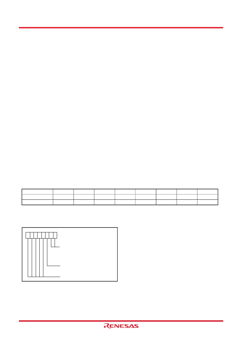
[CPU mode register] CPUM
The CPU mode register contains the stack page selection bit.
This register is allocated at address 003B
16
.
Fig 7.
Structure of CPU mode register
The processor mode bits can be written only once after releasing reset.
Always set them to “00
2
”. After written, rewriting any data to these
bits is disabled because they are locked. (Emulator MCU is excluded.)
Also, the stack page bit (bit 2) is not locked.
In order to prevent error-writing to the processor mode bits (at
program runaway), write the CPU mode register at the start of
the program that runs after releasing reset.
Table 5
Set and clear instructions of each bit of processor status register
C flag
SEC
CLC
Z flag
I flag
SEI
CLI
D flag
SED
CLD
B flag
T flag
SET
CLT
V flag
CLV
N flag
Set instruction
Clear instruction
CPU mode register
(CPUM: address 003B
16
, initial value: 00
16
)
Processor mode bits
b1b0
0 0 :
Single-chip mode
0 1 :
Not available
1 0 :
Not available
1 1 :
Not available
Stack page selection bit
0 : 0
page
1 : 1
page
Disable (returns “0” when read
)
b7
b0
相关PDF资料 |
PDF描述 |
|---|---|
| 75HQ | SCHOTTKY RECTIFIER |
| 75HQ030 | SCHOTTKY RECTIFIER |
| 75HQ035 | SCHOTTKY RECTIFIER |
| 75HQ040 | SCHOTTKY RECTIFIER |
| 75HQ045 | SCHOTTKY RECTIFIER |
相关代理商/技术参数 |
参数描述 |
|---|---|
| 7549_0710 | 制造商:RENESAS 制造商全称:Renesas Technology Corp 功能描述:SINGLE-CHIP 8-BIT CMOS MICROCOMPUTER |
| 7549_09 | 制造商:RENESAS 制造商全称:Renesas Technology Corp 功能描述:SINGLE-CHIP 8-BIT CMOS MICROCOMPUTER |
| 7-5-4905 | 功能描述:3M 4905 VHB TAPE SPECIALTY TAPES 制造商:3m (tc) 系列:VHB?? 4905 零件状态:在售 厚度 - 粘合剂:- 厚度 - 底布,载体:- 标准包装:1 |
| 754905-1 | 功能描述:PIN ATT/ROLL AUTO IV 制造商:te connectivity amp connectors 系列:* 零件状态:有效 标准包装:1 |
| 7-5-4910 | 功能描述:3M 4910 VHB TAPE SPECIALTY TAPES 制造商:3m (tc) 系列:VHB?? 4910 零件状态:在售 底布,载体:丙烯酸泡棉 厚度 - 粘合剂:- 厚度 - 底布,载体:- 标准包装:1 |
发布紧急采购,3分钟左右您将得到回复。